
Satellite ground micro-vibration test system

A test system and micro-vibration technology, applied in measuring devices, measuring ultrasonic/sonic/infrasonic waves, instruments, etc., can solve the problems of mixed real signals, low frequency of micro-vibration signals, difficult data processing and analysis, etc., to improve anti-interference ability, improve signal accuracy, and the effect of high anti-interference ability

Inactive Publication Date: 2012-11-28
SHANGHAI SATELLITE ENG INST
View PDF2 Cites 16 Cited by
  • Summary
  • Abstract
  • Description
  • Claims
  • Application Information

AI Technical Summary

Problems solved by technology

[0004] Due to the low frequency and small amplitude of the micro-vibration signal, the real signal cannot be effectively collected by ordinary measuring instruments, which causes the real signal to be mixed in the noise, which makes further data processing and analysis difficult, and even leads to wrong conclusions. The collection of micro-vibration signals can no longer be satisfied by using traditional vibration testing equipment
[0005] After searching the existing technology, it is found that there is no mature and effective micro-vibration test system in China, such as the document "Spacecraft Micro-vibration Signal Ground Test Method", Spacecraft Environmental Engineering, published in February 2011. and some information about micro-vibration test equipment, but its implementation is still based on traditional acquisition equipment. When the amplitude is lower, the acquisition of micro-vibration signals cannot be realized.

Method used


Image

  • Satellite ground micro-vibration test system
  • Satellite ground micro-vibration test system

Examples


Embodiment Construction

[0043] The embodiments of the present invention are described in detail below: the present embodiment is implemented under the premise of the technical solution of the present invention, and detailed implementation and specific operation process are provided, but the protection scope of the present invention is not limited to the following implementation example.

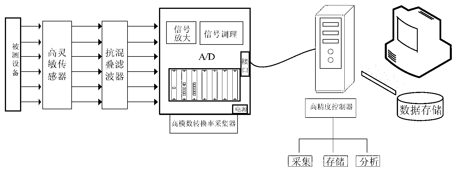
[0044] This embodiment includes a high-sensitivity sensor, an anti-aliasing filter, a high-analog-to-digital conversion rate collector, and a high-precision controller. The high-sensitivity sensor is connected to an anti-aliasing filter, and the anti-aliasing filter is connected to a high The analog-to-digital conversion rate collector is connected, and the high-analog-to-digital conversion rate collector is connected with a high-precision controller, wherein:

[0045] - Highly sensitive sensor for extracting vibration signals near disturbance sources / loads;

[0046] -Anti-aliasing filter, used for anti-aliasing fi...


PUM

PropertyMeasurementUnit
Sensitivityaaaaaaaaaa

Abstract

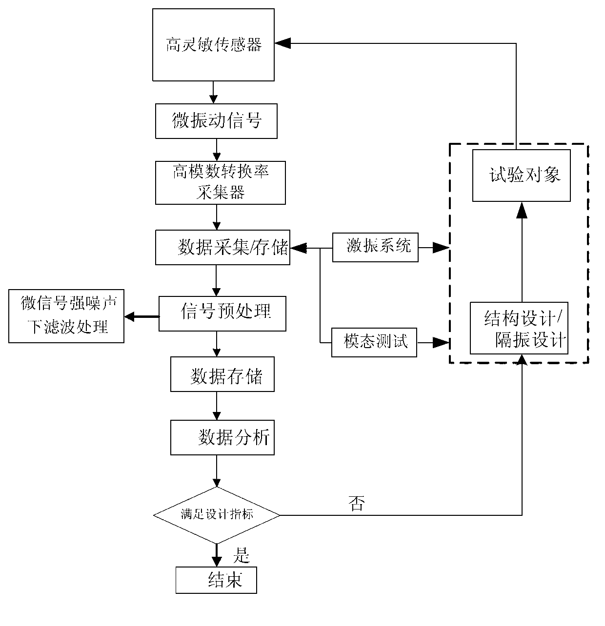
The invention discloses a satellite ground micro-vibration test system. The satellite ground micro-vibration test system comprises a high-sensitivity sensor used for extracting vibration signals near a disturbance source or a load, an anti-aliasing filter used for performing anti-aliasing filtering on the vibration signals extracted by the high-sensitivity sensor to form piezoelectric signals, a high-modulus conversion rate acquirer used for generating the piezoelectric signals into digital signals and a high-precision controller used for controlling display, storage and analysis of the digital signals. According to the invention, the high-sensitivity sensor realizes small-magnitude acquisition of the vibration signals, digital signals are generated through a high-precision data acquisition card after the vibration signals are subjected to the anti-aliasing filtering, and subsequent process is performed to provide efficient input for the subsequent satellite vibration reduction or vibration isolation and environmental test and also realize verification of vibration reduction or vibration isolation performance. Therefore, the satellite ground micro-vibration test system, disclosed by the invention, has the advantages of satisfying demands on acquisition and analysis of micro-vibration signals and being of great importance in improving control precision and stability of a satellite platform.

Description

technical field [0001] The invention relates to the field of vibration testing, in particular to a satellite ground micro-vibration testing system realized by a high-sensitivity acceleration / displacement sensor and high-precision acquisition equipment. Background technique [0002] Micro-vibration, that is, micro-level vibration, is generally acceleration. Since the spacecraft is in a state of weightlessness when it is in orbit, the movement of itself and its payload will cause micro-vibration. The sources of vibration mainly include the work of propellers and moving parts, etc. , its vibration frequency is 0.01~300Hz, and the vibration amplitude is 10 -5 ~10 -2 g level. [0003] With the continuous development of my country's new generation of high-resolution earth observation satellite technology, the sub-systems of sensitive loads and structures on the satellite have gradually realized the serious impact of micro-vibration on sensitive loads. [0004] Due to the low fr...

Claims


Application Information

Patent Timeline
IPC IPC(8): G01H11/06
Inventor 赵发刚周徐斌申军烽顾亦磊杜冬满孝颖
Owner SHANGHAI SATELLITE ENG INST
Learn More