Filter membrane of plasma display panel capable of improving light-room contrast and preparation method of filter membrane

A plasma display, bright room contrast technology, applied in the field of filter films, can solve the problems of many transparent polymer resin substrates and pressure-sensitive adhesives, limiting the visible light transmittance of filter films, and long process routes, etc. Light transmittance and high bright room contrast, improved bright room contrast, less process flow

Inactive Publication Date: 2012-11-28
TIANNUO PHOTOELECTRIC MATERIAL +1
View PDF5 Cites 6 Cited by
  • Summary
  • Abstract
  • Description
  • Claims
  • Application Information

AI Technical Summary

Problems solved by technology

[0005] Since this kind of CRF filter film has a structure of double-layer transparent polymer resin substrates A1, B1 and double-layer adhesive film layers A2, B3, more transparent polymer resin substrates and pressure-sensitive adhesives are used.

Method used


Image

  • Filter membrane of plasma display panel capable of improving light-room contrast and preparation method of filter membrane
  • Filter membrane of plasma display panel capable of improving light-room contrast and preparation method of filter membrane
  • Filter membrane of plasma display panel capable of improving light-room contrast and preparation method of filter membrane

Examples


Embodiment 1

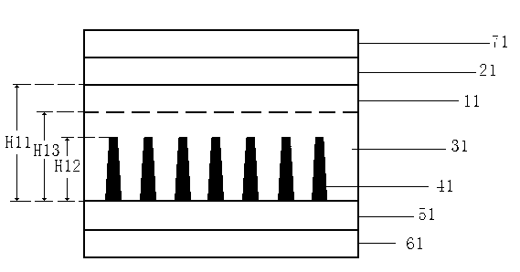
[0020] Embodiment 1: as image 3 As shown, the plasma display filter film includes a substrate 11, one surface of the substrate 11 is provided with an anti-reflection (AR) film layer 21, and the substrate 11 is provided with stripe pattern grooves, A black filler 41 is provided inside the stripe pattern groove, a Color-PSA adhesive film layer 51 is arranged outside the stripe pattern groove, and the stripe pattern groove is arranged on the substrate 11 Between the Color-PSA adhesive film layer 51, the substrate 11 is transparent, the stripe pattern groove is a trapezoid gradually narrowing from the outside to the inside, and the anti-reflection ( AR) The surface of the film layer 21 is provided with a protective film layer 71, the surface of the Color-PSA adhesive film layer 51 is provided with a release film layer 61, and the composition of the Color-PSA adhesive film layer 51 includes UV absorber, near-infrared light-absorbing dye, neon yellow light-absorbing dye, toning dy...

Embodiment 2

[0024] like Figure 4 As shown, the plasma display filter film includes a substrate 12, one surface of the substrate 12 is provided with an anti-reflection (AR) film layer 22, and the substrate 12 is provided with a stripe pattern groove, A black filler 42 is provided inside the stripe pattern groove, a Color-PSA adhesive film layer 52 is arranged outside the stripe pattern groove, and the stripe pattern groove is arranged on the substrate 12 Between the Color-PSA adhesive film layer 52, the substrate 12 is transparent, the stripe pattern groove is a triangle that gradually narrows from the outside to the inside, and the anti-reflection ( AR) The surface of the film layer 22 is provided with a protective film layer 72, the surface of the Color-PSA adhesive film layer 52 is provided with a release film layer 62, and the composition of the Color-PSA adhesive film layer 52 includes UV absorber, near-infrared light-absorbing dye, neon yellow light-absorbing dye, toning dye and ac...


PUM

PropertyMeasurementUnit
Thicknessaaaaaaaaaa

Abstract

The invention provides a filter membrane of a plasma display panel and a preparation method of the filter membrane and relates to a filter membrane technique for improving a contrast of a display. The filter membrane solves problems that such traditional filter membrane has the disadvantages of many membrane layers, low transmittance of visible lights, complex processing, low efficiency and high cost. The filter membrane comprises a substrate, wherein an anti-reflective membrane layer or a hardening membrane layer is arranged on one side of the substrate; the substrate is provided with stripe-patterned grooves, in which black fillers are arranged; Color-PSA adhesive membrane layers are arranged outside the grooves; the preparation method of the filter membrane comprises the following steps of: manufacturing the anti-reflective membrane layer or the hardening membrane layer on one side of the substrate, manufacturing stripe-patterned grooves and black fillers on one side of the substrate and manufacturing the Color-PSA adhesive membrane layers outside the grooves. The filter membrane provided by the invention has the advantages of less membrane layers, light weight, capability of high transmittance and light-room contrast, low cost, simple preparation method, high qualified rate of filter membranes and high production efficiency. The filter membrane provided by the invention is mainly applied to plasma display panels.

Description

technical field [0001] The invention relates to a filter film technology, in particular to a filter film which can be used to improve the contrast ratio of a plasma display (PDP) in a bright room and a preparation method thereof. Background technique [0002] Plasma display (PDP) display technology is to discharge the working gas such as neon gas and xenon gas inside the display by applying voltage, so as to emit ultraviolet light of a specific band, and use the ultraviolet light of this specific band to excite the phosphor layer to emit red and green. , Blue three primary color light display technology. However, in the process of the PDP display emitting light, in addition to the visible light of the three primary colors of red, green and blue, it will also produce near-infrared rays that seriously interfere with the TV remote control and shutter 3D glasses; secondly, the neon gas inside the PDP display is discharged in the PDP. Yellow light will be produced during the pro...

Claims


Application Information

Patent Timeline
IPC IPC(8): G02B5/20H01J11/44H05K9/00
Inventor 朱焰焰潘晓勇房海波李斌李昌林舒宝张颖彭德权刘佳其
Owner TIANNUO PHOTOELECTRIC MATERIAL
Why Eureka
Try Eureka