
Light-emitting diode driving apparatus including charging/discharging capacitor

A technology of light-emitting diodes and driving devices, which is applied in the direction of electroluminescent light source, electric lamp circuit layout, electric light source, etc., can solve the problems of power factor deterioration, power supply efficiency deterioration, constant current circuit loss increase, etc., to achieve uniformity , Improve the effect of crest factor

Active Publication Date: 2012-11-28
NICHIA CORP
View PDF3 Cites 21 Cited by
  • Summary
  • Abstract
  • Description
  • Claims
  • Application Information

AI Technical Summary

Problems solved by technology

In this constant current LED driving circuit, there is the following problem: if the total V of multiple LED elements f If it is low, the loss in the constant current circuit due to the voltage difference from the peak voltage of the pulsating current (141V in Japan) increases and the power supply efficiency deteriorates
In order to solve the above problems, it can be achieved by using a large-capacity capacitor to smooth the pulse current, but there are concerns about the deterioration of the power factor and the inrush current when the power is turned on due to the rapid charging current that rapidly charges the capacitor.
[0006] In this way, in the case of using an AC power supply to directly drive the LED with the rectified pulse current, it is difficult to achieve a balance between power supply efficiency, power factor, LED utilization efficiency, and light output peak factor
In particular, if Figure 20 It can be seen that due to the power supply efficiency and LED utilization efficiency relative to the V of the LED f has an inverse relationship, so only compromise points have been found to strike the right balance
In addition, in order to improve the peak factor of the light output, the LED utilization efficiency can be improved by extending the lighting period due to the discharge of the capacitor, but there is a problem that the power factor deteriorates due to the charging current of the capacitor.

Method used


Image

  • Light-emitting diode driving apparatus including charging/discharging capacitor
  • Light-emitting diode driving apparatus including charging/discharging capacitor
  • Light-emitting diode driving apparatus including charging/discharging capacitor

Examples


Embodiment approach 1

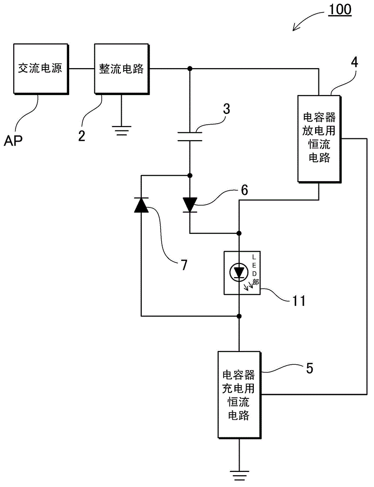
[0040] figure 1 A block diagram of the light emitting diode driving device 100 according to Embodiment 1 of the present invention is shown. This light emitting diode driving device 100 includes a rectifier circuit 2 , a first LED unit 11 , a capacitor charging constant current circuit 5 , a capacitor discharging constant current circuit 4 , a charging diode 6 , a discharging diode 7 , and a charging and discharging capacitor 3 . This light emitting diode driving device 100 is connected to an AC power supply AP, and obtains a rectified voltage (pulsating current voltage) obtained by rectifying the AC voltage in the rectifying circuit 2 . In addition, between the AC power supply AP and the rectifier circuit 2, a fuse 81 for preventing overcurrent or a surge protection circuit for preventing overvoltage can also be provided.

[0041] The LED section is a block in which one or more LED elements are connected in series and / or in parallel. As the LED element, a surface mount type...

Embodiment approach 2

[0052] Specifically, in figure 1 In the example of , an example using one LED unit was described, but a plurality of LED units may also be used. It is also possible to connect a plurality of LED units in series, and to add an LED unit to the charge path CP, to add an LED unit to the discharge path DP, or to add an LED unit to each of the charge path CP and the discharge path DP. Here, as Embodiment 2, in Figure 6 A circuit example in which the second LED unit 12 is added to the charge path CP and the third LED unit 13 is added to the discharge path DP is shown in FIG. In this way, it is possible to change the combination of the LED units that are lit (the number of LED units that emit light) during each of the capacitor charging period, the capacitor discharging period, and the transition period between the two periods. Thus, the power efficiency can be further improved and the LED voltage V f freedom of setting.

[0053] As above, according to V c+ =V che -V f and V ...

Embodiment 1

[0058] Next, at Figure 13 The light-emitting diode driving device 100' shows the composition of figure 1 A specific example of the circuit of the light emitting diode driving device 100 according to Embodiment 1 is described in Figure 14 The light emitting diode driving device 200' shows the same structure Figure 6 A specific example of the circuit of the light emitting diode driving device 200 according to the second embodiment. In each circuit example 100', 200', the basic operation has been described as above. Here, the operation of the light emitting diode driving device 200' according to the second embodiment will be mainly described. In addition, the operation of the light-emitting diode driving device 100' of the first embodiment is substantially the same as that of the light-emitting diode driving device 200' of the second embodiment, because the first LED part 11, the second LED part 12, and the third LED part 13 can be In other words the first LED section 11,...


PUM


Abstract

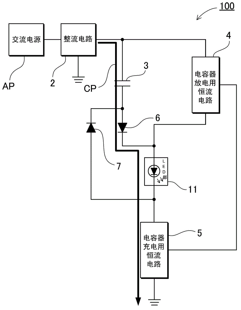
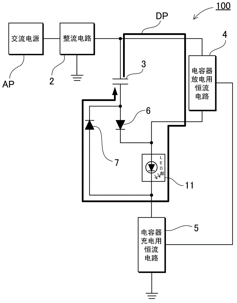
A charging diode 6 is connected to the capacitor 3 and the anode of a first LED 11, and limits the direction of the charging current. A discharging diode 7 is connected to the capacitor 3 and the cathode of the first LED 11, and limits the direction of the discharging current. A charging path CP is provided which includes the capacitor 3, the charging diode 6, and the charger 5. The capacitor 3 is charged through the charging path CP. A discharging path DP is provided which includes the capacitor 3, the discharging diode 7 and a discharger 4. The capacitor 3 is discharged through the discharging path DP. A transient path TP is provided which does not include the capacitor 3 but includes the first LED 11, the charger 5 and the discharger 4.

Description

technical field [0001] The present invention relates to a driving circuit for driving a light-emitting diode, in particular to a driving device for a light-emitting diode driven by an AC power supply. Background technique [0002] In recent years, light-emitting diodes (hereinafter also referred to as "LEDs") that can be driven with lower power consumption than incandescent lamps and fluorescent lamps have attracted attention as light sources for lighting. The advantages of LEDs are: small size, strong impact resistance, no worries about thermal cracking of light bulbs, etc. As a power source for such lighting equipment, AC power such as a household power source is expected to be used as a power source. On the other hand, LED is a DC drive element, and only the forward current will emit light. In addition, the forward voltage V of LEDs that are often used for lighting purposes f It is about 3.5V. LED has f It will not emit light, on the contrary if it exceeds V f A cha...

Claims


Application Information

Patent Timeline
Patent Type & Authority Applications(China)
IPC IPC(8): H05B37/02
CPCH05B33/0824Y02B20/341Y02B20/345H05B33/0812H05B37/02H05B45/395H05B45/44Y02B20/30
Inventor 樱木晴海小椋涉渡边照雄
Owner NICHIA CORP
Learn More