Reader-writer, electronic tag and radio frequency identification system

An electronic tag, radio frequency identification technology, applied in the field of readers, electronic tags and radio frequency identification systems, can solve the problems of versatility, performance differences, antenna performance differences, etc.

Inactive Publication Date: 2012-12-05
KUANG CHI INST OF ADVANCED TECH +1
View PDF6 Cites 5 Cited by
  • Summary
  • Abstract
  • Description
  • Claims
  • Application Information

AI Technical Summary

Problems solved by technology

There are large differences in the working environment and electromagnetic characteristics of antennas in different products, which will lead to large differences in antenna performance in design and use. Therefore, the designed antenna must have strong adaptability and universality. sex
To sum up, the original technology will encounter problems of versatility and performance differences in use

Method used


Image

  • Reader-writer, electronic tag and radio frequency identification system
  • Reader-writer, electronic tag and radio frequency identification system
  • Reader-writer, electronic tag and radio frequency identification system

Examples


Embodiment 2

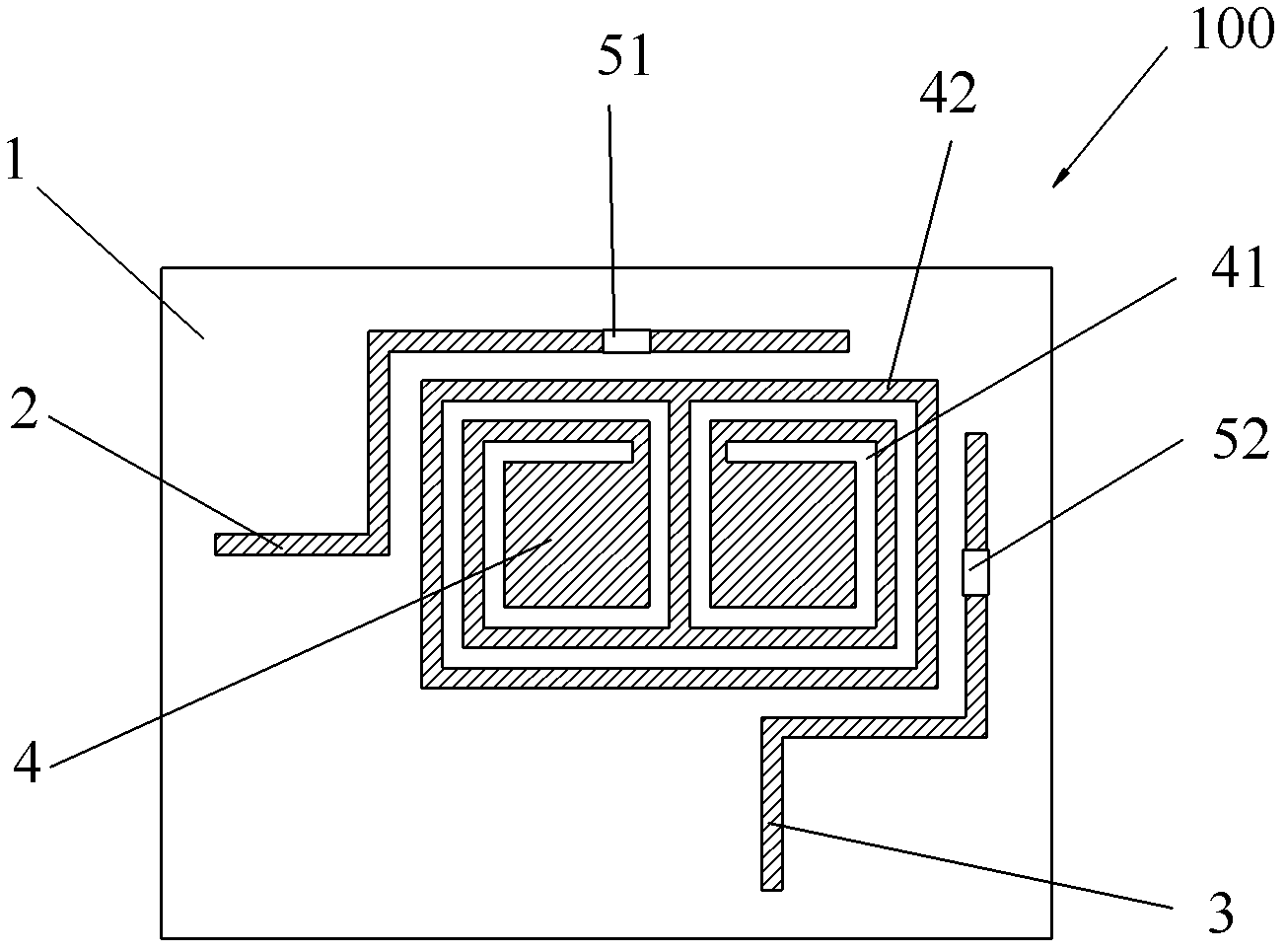
[0047] Such as image 3 As shown, in this embodiment, between the first feeder line 2 and the metal sheet 4, and between the second feeder line 3 and the metal sheet 4, a space 53, and a space 54 for embedding capacitive electronic components are preset. The position of the electronic component space can be any position between the first feeder 2 and the metal sheet 4 and between the second feeder 3 and the metal sheet 4. image 3 The middle space 53 and the space 54 are the spaces where capacitive electronic components are embedded in this embodiment. There is a certain capacitance between the first feeder line 2, the second feeder line 3 and the metal sheet 4, and the first The signal coupling between the feeder 2, the second feeder 3 and the metal sheet 4, using the formula: It can be seen that the size of the capacitance value is inversely proportional to the square of the operating frequency, so when the required operating frequency is a lower operating frequency, it can be...

Embodiment 3

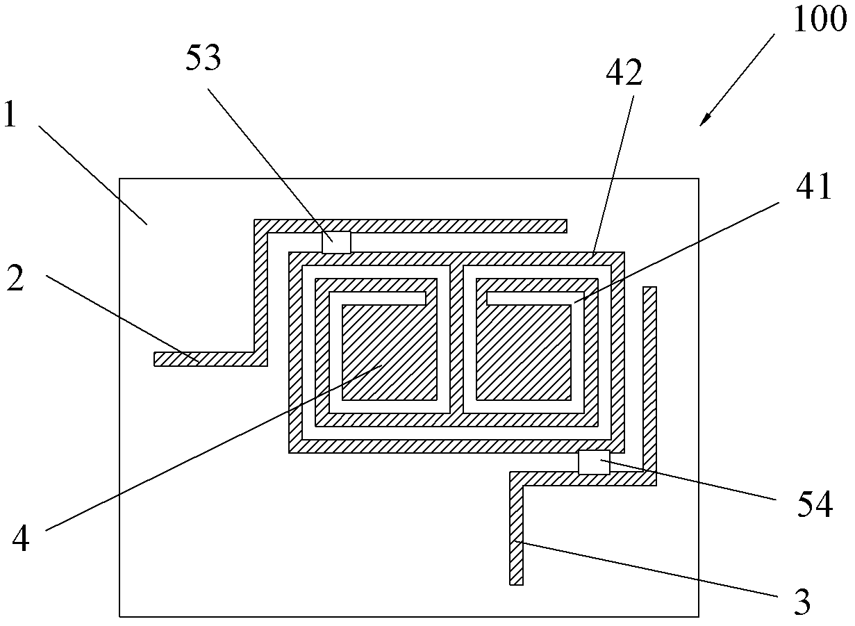
[0049] Such as Figure 4 As shown, in this embodiment, a space for embedding inductive electronic components and / or resistors is reserved on the metal trace 42 of the metal sheet, and the space for embedding electronic components is not limited to the space 55 and the space given in the figure. 56, other locations as long as the conditions are met. The purpose of embedding inductive electronic components here is to increase the inductance value of the internal resonant structure of the metal sheet, thereby adjusting the resonant frequency and working bandwidth of the antenna; as in the first embodiment, the purpose of embedding resistors here is to improve the antenna’s Radiation resistance. As for whether to embed inductive electronic components or resistors, it depends on the needs. In addition, in the space where electronic components are not embedded, wire shorting is used.

Embodiment 4

[0051] Such as Figure 5 As shown, in this embodiment, a space 57 for embedding capacitive electronic components is reserved on the microgroove structure 41, and the space 57 is connected to the metal traces 42 on both sides of the microgroove structure 41. The space for embedding electronic components is not limited to Figure 5 The space 57 given in, other locations as long as they meet the conditions. Embedding capacitive electronic components can change the resonance performance of the metal sheet, and ultimately improve the Q value and resonance operating point of the antenna. As common knowledge, we know that the relationship between the passband BW and the resonant frequency w0 and the quality factor Q is: BW=wo / Q. This formula shows that the larger the Q, the narrower the passband, and the smaller the Q, the wider the passband. In addition: Q = wL / R = 1 / wRC, where Q is the quality factor; w is the power supply frequency when the circuit is resonant; L is the inductance;...


PUM


Abstract

The invention relates to a reader-writer, an electronic tag and a radio frequency identification system. The reader-writer is communicated with the electronic tag, and comprises a radio frequency identification reader-writer antenna, wherein the radio frequency identification reader-writer antenna comprises a medium substrate, a first feeder line, a second feeder line, and a metal sheet attached to a surface of the medium substrate, the first feeder line and the second feeder line are both fed in the metal sheet in a coupling mode, a microgroove structure is hollowed out on the metal sheet for forming metal line wiring on the metal sheet, and the antenna is pre-provided with a space used for embedding an electronic component. The invention also relates to the electronic tag and the radio frequency identification system. According to the technical scheme disclosed by the invention, the antenna of the reader-writer and the electronic tag is provided with the space for embedding the electronic component, the performance of the antenna can be finely adjusted by changing the performance of the embedded electronic component, and the antenna satisfying the requirements on adaptability and generality is designed to be used on various radio frequency identification application occasions.

Description

Technical field [0001] The invention belongs to the field of communication, and specifically relates to a reader, an electronic tag and a radio frequency identification system. Background technique [0002] Radio Frequency Identification (RFID) is a non-contact automatic identification technology. Its basic principle is to use the transmission characteristics of radio frequency signals and spatial coupling (inductive or electromagnetic coupling) or radar reflection to realize automatic identification of identified objects. . [0003] The RFID system includes at least two parts: an electronic tag and a reader. The electronic tag is attached to the object and contains a unique ID number and information about the item; the reader is used to read the information on the electronic tag to realize automatic identification of the object. When the RFID system is working, the reader sends a radio frequency signal through the reader antenna. After the electronic tag receives the read and wri...

Claims


Application Information

Patent Timeline
Patent Type & Authority Applications(China)
IPC IPC(8): G06K17/00G06K19/077H01Q1/22H01Q1/38
Inventor 刘若鹏徐冠雄
Owner KUANG CHI INST OF ADVANCED TECH
Why Eureka
Try Eureka