Residual oil hydrotreating process

A technology for hydrogenation and treatment of residue oil, which is applied in the fields of hydrotreating process, petroleum industry, treatment of hydrocarbon oil, etc., can solve the problems of large coke generation, reducing the treatment capacity of the device and economic benefits, and increasing the load of the regenerator.

Inactive Publication Date: 2012-12-12
PETROCHINA CO LTD
View PDF8 Cites 22 Cited by
  • Summary
  • Abstract
  • Description
  • Claims
  • Application Information

AI Technical Summary

Problems solved by technology

Because the heavy cycle oil contains polycyclic aromatic hydrocarbons, the yield of light oil is low and the amount of coke is large, which increases the load of the regenerator and reduces the processing capacity and economic benefits of the unit.

Method used


Image

  • Residual oil hydrotreating process
  • Residual oil hydrotreating process
  • Residual oil hydrotreating process

Examples


Embodiment 1

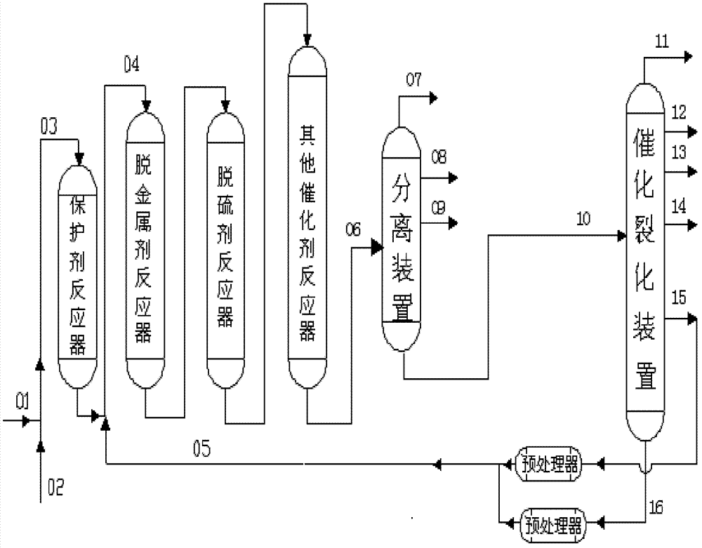
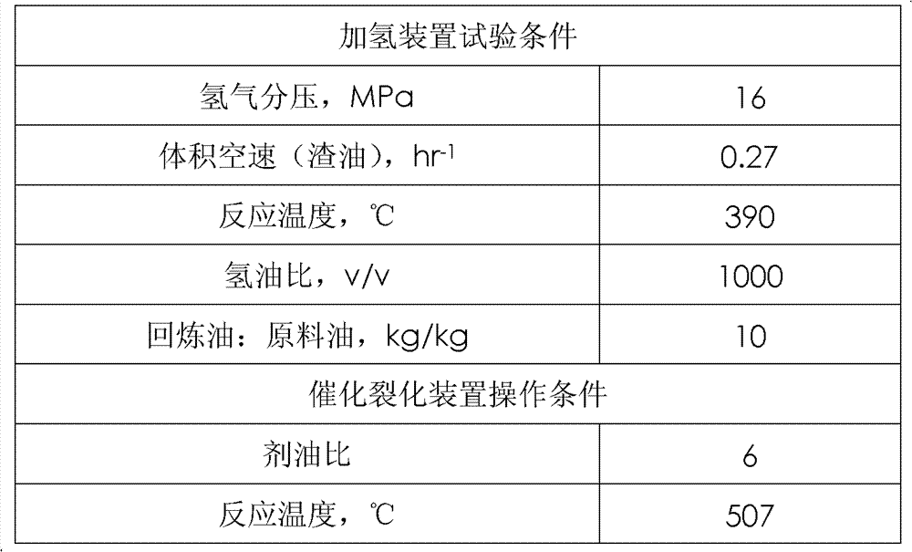
[0037] The residual oil and hydrogen mixed oil directly enter the residual oil hydrogenation pilot plant, and the catalytic cracking back to the refinery uses the filtered catalytic cracking heavy cycle oil, which enters the residual oil hydrogenation reactor through the front feed port of the demetallization agent bed, and also according to the table The reaction is carried out under the conditions in 3, and the reaction products are separated into gas, hydrogenated naphtha, hydrogenated diesel oil, and hydrogenated residue; the hydrogenated residue enters the catalytic cracking unit to continue the reaction, and the products are separated into dry gas, catalytic gasoline, catalytic Diesel, heavy cycle oil, oil slurry. See Table 3 for product properties and operating conditions.

Embodiment 2

[0044] The residual oil and hydrogen mixed oil directly enter the residual oil hydrogenation pilot plant, and the catalytic cracking oil refining uses catalytic cracking oil slurry. After filtering, it enters the residual oil hydrogenation reactor through the front feed port of the demetallization agent bed, and also according to the table The reaction is carried out under the conditions in 1, and the reaction products are separated into gas, hydrogenated naphtha, hydrogenated diesel oil, and hydrogenated residue; the hydrogenated residue enters the catalytic cracking unit to continue the reaction, and the products are separated into dry gas, catalytic gasoline, catalytic Diesel, heavy cycle oil, oil slurry. The properties and operation of the product are shown in Table 4.

Embodiment 3

[0051] The residual oil and hydrogen mixed oil directly enter the residual oil hydrogenation pilot plant, and the catalytic cracking and refining oil adopts catalytic cracking heavy cycle oil: catalytic cracking oil slurry: 5:5, after filtering, it enters through the front feed port of the demetallizer bed The residual oil hydrogenation reactor also reacts according to the conditions in Table 1, and the reaction products are separated into gas, hydrogenated naphtha, hydrogenated diesel oil, and hydrogenated residual oil; the hydrogenated residual oil enters the catalytic cracking unit to continue the reaction, The products are separated into dry gas, catalytic gasoline, catalytic diesel, heavy cycle oil and oil slurry. The properties and operation of the product are shown in Table 5.


PUM


Abstract

The invention relates to a residual oil hydrotreating process. A feeding port is added in front of a demetalization agent bed layer of a residual oil hydrotreater, residual oil and hydrogen enter the device to react through a raw material feeding port of the residual oil hydrotreater, and catalytic cracking recycle oil enters the device to react through the added feeding port. The residual oil hydrotreater adopts catalyst grading loading, is filled with three or more catalysts including a protective agent, a demetalization agent and a desulfurizing agent sequentially, each catalyst is filled into one bed layer, and the protective agent adopts an up-flow type reactor or a fixed bed reactor. By means of the method, impurity removing rate in residual oil hydrotreating can be improved, an operation period of the residual oil hydrotreater can be prolonged, and the yield of light liquid with high added value can be improved.

Description

technical field [0001] The invention relates to a combined process of hydrogenation treatment and catalytic cracking of residual oil. Background technique [0002] At present, the world's oil refining and processing industry is facing the severe challenge of increasingly heavy and inferior crude oil resources. In 2008, my country's crude oil processing volume was 342 million tons, of which heavy crude oil processing volume reached 137 million tons, accounting for more than 40% of the total. As we all know, the proportion of residual oil in crude oil is usually 45-75%, and its properties are significantly inferior to fractions such as gas oil with a lower boiling range. Therefore, the pressure for deep processing of crude oil to maximize the production of light products and chemical raw materials naturally falls on on the residual oil. [0003] Among the optional technical routes for deep processing of residual oil, the combined process of residual oil hydrogenation and cat...

Claims


Application Information

Patent Timeline
Patent Type & Authority Applications(China)
IPC IPC(8): C10G69/04
Inventor 赵愉生崔瑞利于双林程涛谭青峰赵元生周志远范建光张春光张志国那美琦刘元东
Owner PETROCHINA CO LTD
Why Eureka
Try Eureka