Solid heat storage device

A heat storage device and solid technology, applied in heating devices, solar thermal devices, solar heat storage, etc., can solve problems such as short service life, large heat loss in external pipeline insulation cycles, and limited heat transfer area between solids. Reach the effect of reducing the energy consumption of the system operation, ensuring the quality of heat output, and good overall heat transfer performance

Inactive Publication Date: 2012-12-12
BEIJING TERASOLAR PHOTOTHERMAL TECH CO LTD
View PDF5 Cites 40 Cited by
  • Summary
  • Abstract
  • Description
  • Claims
  • Application Information

AI Technical Summary

Problems solved by technology

At present, the existing industrialized solar thermal power generation units mostly use inorganic salts as heat storage materials, but inorganic salts have the disadvantages of supercooling and phase separation during the phase transition process, which affects the heat storage capacity, and its solidification temperature is too high, As a result, the heat loss of the external pipeline insulation cycle is large at night to ensure that it does not solidify. Once the system freezes, it is difficult to dispose of it, and there are potential safety hazards; the pumps and valves used in the pipeline of the molten salt system are expensive and have a relatively long service life. Short, and the inorganic salt has certain toxicity, and it is easy to leak and cause a fire, and the leakage will pollute the environment
Solid-state heat storage solutions include concrete and cobblestone heat storage, etc., pouring heat exchange pipes inside the concrete, the cost is high, and the heat transfer coefficient is very low, etc.; sandstone heat storage, although the price is cheap, but the thermal conductivity is low, heat transfer Difficult, unable to shape and self-support, affecting use; and the existing solid heat storage scheme is to arrange the heat exchange pipe inside the solid heat storage material, and complete the heat transfer through the heat conduction between the solid and the solid on the surface of the pipe or fin surface and the surface of the heat storage material , due to the incomplete contact between solids, and the poor thermal conductivity of solid heat storage materials, and the limited heat transfer area between solids, the overall heat conduction efficiency is low, so it is difficult to meet the input power requirements for heat storage In more cases, the heat of the heat transfer medium has already flowed out of the solid heat storage system before it is completely released in the solid heat storage system, and the heat storage function of the solid heat storage system cannot be completed satisfactorily according to the required power.

Method used


Image

  • Solid heat storage device
  • Solid heat storage device
  • Solid heat storage device

Examples


Embodiment Construction

[0053] The present invention will be further described in detail below in conjunction with the examples.

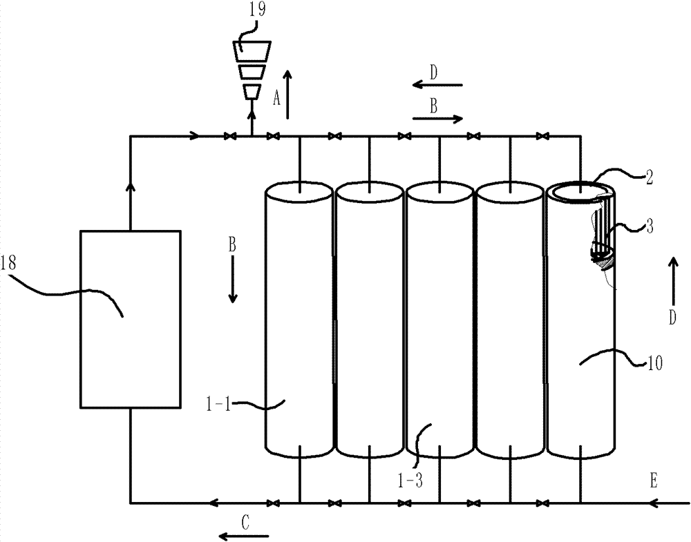
[0054] figure 1 It is a schematic diagram of the overall structure of an embodiment of a solid heat storage device of the present invention; the solid heat storage device is composed of a plurality of heat storage units, such as an array of heat storage units 1-1 and heat storage units 1-3; figure 1 As shown, the heat storage units 1-1 of the array are arranged vertically on the ground; each heat storage unit 1-1 includes a casing 2, a solid heat storage medium 3 arranged inside the casing 2, and an insulation layer 10 arranged outside the casing 2; The outer surface of the solid heat storage medium 3 is the heat exchange interface of the heat transfer medium, and the solid heat storage medium 3 is a dense material with a porosity of less than 10%; optimally, the surface of the solid heat storage medium 3 has an airtight layer to further reduce the heat transfer medium i...


PUM


Abstract

The invention provides a solid heat storage device which is formed by combining at least one heat storage unit in series and / or parallel. The heat storage unit comprises a casing, a solid heat storage medium arranged in the casing and a heat insulation layer arranged outside the casing. The outer surface of the solid heat storage medium is a heat exchange interface. Heat insulation layers are regularly arranged in the heat storage unit, an inclined temperature layer is arranged in the axial direction, and a layering control system is arranged in the heat storage unit to ensure high grade storage and output of heat. The heat storage unit of an array can be vertically arranged and can also be horizontally arranged with a certain inclined angle. The solid heat storage medium utilizes solid sensible heat to store heat, and is safe in running, simple to process and low in cost. The surface of the solid heat storage medium has good heat exchange efficiency and good heat storage performance and can be widely applied to various heat storage applications, especially a solar photo-thermal utilization system.

Description

technical field [0001] The invention relates to a solid heat storage device, in particular to a heat storage device in a solar photothermal utilization system. Background technique [0002] Solar energy is an ideal clean energy source, but there is a problem of timeliness in utilization. The energy received during the sunshine period is more than required, but it cannot function after sunset. Therefore, how to store the excess energy during sunshine for the continuous operation of the system after sunset, that is, to take the excess to make up for the deficiency, has become a key issue in realizing the continuous operation of the solar thermal utilization device. [0003] In the existing solar energy storage technologies, various heat storage media have been reported or used. In recent years, it has been reported that a composite phase-change material (shape-fixed phase-change material) supported by a specific material as a matrix has been obtained in the laboratory to stor...

Claims


Application Information

Patent Timeline
Patent Type & Authority Applications(China)
IPC IPC(8): F28D20/00F24J2/46F24J2/34
CPCF28D20/0056Y02E10/40F24J2/46F28D20/0039F28D2020/0082Y02E70/30F28D20/00F24J2/34Y02E60/142C09K5/14F24S60/00F28F2270/00Y02E60/14Y02P20/10
Inventor 刘阳
Owner BEIJING TERASOLAR PHOTOTHERMAL TECH CO LTD
Why Eureka
Try Eureka