Improved oxide-film resistance changing memory and improvement method thereof

A technology of resistive variable memory and oxide thin film, which is applied in the direction of electrical components, etc., can solve the problems of fatigue, stability and uniformity obstacles of new resistive variable memory

Inactive Publication Date: 2012-12-12
TONGJI UNIV
View PDF4 Cites 7 Cited by
  • Summary
  • Abstract
  • Description
  • Claims
  • Application Information

AI Technical Summary

Problems solved by technology

[0005] However, compared with the traditional flash memory technology that has been industrialized and applied to actual electronic products on a large scale, the fatigue, stability and uniformity of the new resistive memory are the biggest obstacles to its application in actual products

Method used


Image

  • Improved oxide-film resistance changing memory and improvement method thereof
  • Improved oxide-film resistance changing memory and improvement method thereof
  • Improved oxide-film resistance changing memory and improvement method thereof

Examples


Embodiment 1

[0043] Example 1 Preparation of Improved Oxide Thin Film Resistive Variable Memory

[0044] method one:

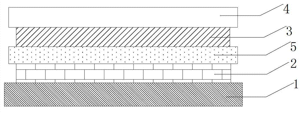
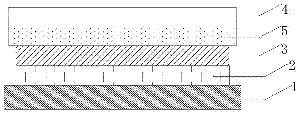
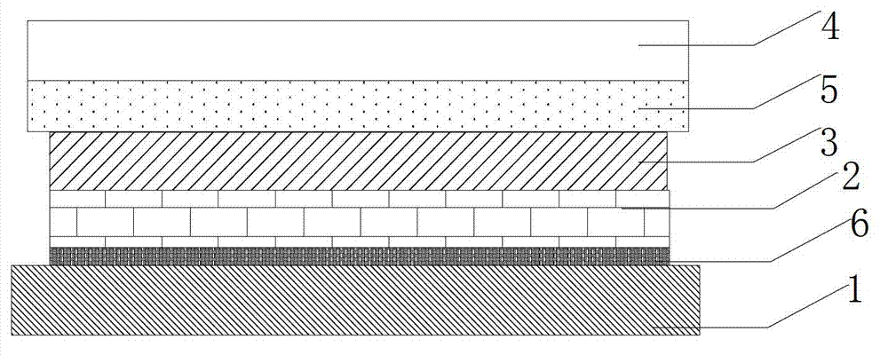
[0045] In SiO 2 On the Si insulating substrate, a 10nm adhesion layer Ti, a 50nm bottom electrode W, and a 100nm metal oxynitride interface layer WO were sequentially deposited by magnetron sputtering. 0.1 N 0.8 , 40nm oxide resistive layer TaO 1.8 , 50nm top electrode Pt, and the obtained RRAM is marked as memory A.

[0046] Method Two:

[0047] Using the same deposition method and materials as method one to prepare a device without a metal oxynitride interface layer, the steps are: on SiO 2 On the / Si insulating substrate, a 10nm adhesion layer Ti, a 50nm bottom electrode W, and a 40nm oxide resistive layer TaO were sequentially deposited by magnetron sputtering 1.8 , 50nm top electrode Pt, prepared and obtained a resistive variable memory with a sandwich structure of "bottom electrode / oxide film / top electrode" as a control, marked as memory A'.

[0048] Method th...

Embodiment 2

[0054] Example 2 Performance testing of oxide thin film resistive memory

[0055] 1. Efficiency detection of RRAM

[0056] Take the memory A of the first method and the memory A' of the second method in Example 1, and perform DC voltage scanning detection. The experimental results are shown in the current-voltage (I-V) curve diagram of the DC voltage scanning (attached Figure 3-4 ), including the initial soft breakdown (forming), high-impedance state (RESET), and low-impedance state (SET) operation. in image 3 is the I-V curve of a memory device with an interfacial layer, Figure 4 is the I-V plot of a memory device without an interfacial layer.

[0057] Depend on Figure 3-4 The experimental results show that the RESET current of the storage device with the interface layer is small (1 mA), while the RESET current of the storage device without the interface layer is relatively large (about 40 mA). Since the device is easily damaged by a large current, a memory device wi...


PUM

PropertyMeasurementUnit
thicknessaaaaaaaaaa
thicknessaaaaaaaaaa
thicknessaaaaaaaaaa

Abstract

The invention relates to the field of micro-electronics memorizers, and specifically discloses an improved oxide-film resistance changing memory and improvement method thereof. The improved oxide-film resistance changing memory comprises a top electrode, an oxide resistance changing layer, a bottom electrode and an insulating substrate from top to bottom, wherein an interface layer is arranged between the top electrode and the oxide resistance changing layer or the bottom electrode and the oxide resistance changing layer; and a metal nitrogen oxide film is used as the interface layer. According to the introduce of the oxynitride interface layer, on one hand, the low state resistance of the resistance changing memory is improved, so that the storage operation energy consumption is reduced; and on the other hand, the resistance changing generative range is limited, a resistance changing manner is limited, and the purpose for improving fatigue resistance, stability and uniformity of the resistance changing memory is achieved.

Description

technical field [0001] The invention relates to the field of microelectronic memory, and specifically discloses an improved oxide thin film resistance variable memory and an improvement method thereof. Background technique [0002] As portable consumer electronics are used more and more widely, the demand for large-capacity non-volatile memory is becoming more and more urgent. [0003] Traditional Erasable Programmable Read-Only Memory (EPROM) and Electrically Erasable Programmable Read-Only Memory (E2PROM) are far from meeting today's market demand, and flash memory based on floating gate structure is also due to high The operating voltage and complex circuit structure have been criticized by the industry, so various new next-generation non-volatile memories have emerged, such as ferroelectric memory (FeRAM), magnetic memory (MRAM), phase change memory (PRAM), Resistive RAM (RRAM), etc. [0004] Compared with other non-volatile memories, resistive memory is characterized ...

Claims


Application Information

Patent Timeline
Patent Type & Authority Applications(China)
IPC IPC(8): H01L45/00
Inventor 翟继卫周歧刚
Owner TONGJI UNIV
Why Eureka
Try Eureka