Drawing forming device for deep-hole key slot with symmetric double surfaces

A technology of symmetrical keyway and forming device, applied in the direction of broaching machine, broaching machine, broaching tool, etc., can solve the problems of inability to achieve machining accuracy, insufficient tensile strength of driving sleeve, affecting the service life of drilling machine, etc. High precision, improved tensile strength and stiffness

Inactive Publication Date: 2012-12-19
JIANGSU CHANGLI HYDRAULIC CYLINDER
View PDF7 Cites 0 Cited by
  • Summary
  • Abstract
  • Description
  • Claims
  • Application Information

AI Technical Summary

Problems solved by technology

The existing keyway processing of the inner hole is to install a single knife on the push-pull equipment, or use wire cutting and plasma processing to form, but this processing method is greatly limited by the processing length of the equipment within 1m, and the processing accuracy cannot be achieved. Require
It is the United States and the United Kingdom, which are the only countries in the world that can manufacture drilling machines, the length of the drive sleeve in the drilling machine they produce is only 2436mm, the diameter of the inner hole is φ101.5mm, and the two symmetrical keyways in the inner hole are not It is processed as a whole, but first mills out a groove with the same size as the symmetrical keyway on the thin-walled tube, and then inserts the thin-walled tube into the drive sleeve and welds it into one body, which is also limited by the limitation of the processing length of the equipment within 1m , this processing method causes insufficient tensile strength of the drive sleeve, which seriously affects the service life of the drilling machine

Method used


Image

  • Drawing forming device for deep-hole key slot with symmetric double surfaces

Examples


Embodiment Construction

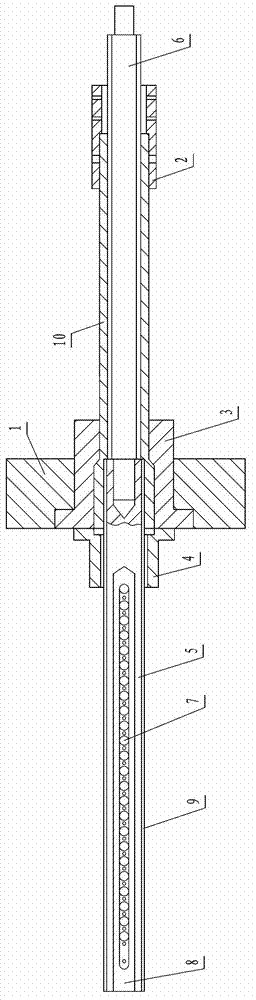
[0012] The present invention will now be further described in conjunction with the accompanying drawings and preferred embodiments. These drawings are all simplified schematic diagrams, which only illustrate the basic structure of the present invention in a schematic manner, so they only show the configurations related to the present invention.

[0013] Such as figure 1 The drawing and forming device for double-sided symmetrical key grooves in deep holes is shown, which is used for drawing and forming double-sided symmetrical key grooves in inner holes of ultra-long shaft tube workpieces. Including the supporting wallboard 1 and the pull rod positioning sleeve 2 fixed on the fuselage of the pulling machine when in use, the supporting wallboard 1 and the pull rod positioning sleeve 2 are set apart and the pull rod positioning sleeve 2 is located on the right side of the supporting wallboard 1, on the supporting wall A workpiece support sleeve 3 is fixed inside the plate 1, and...


PUM


Abstract

The invention discloses a drawing forming device for a deep-hole key slot with symmetric double surfaces. The drawing forming device comprises a supporting wall plate and a draw bar positioning sleeve, the workpiece supporting sleeve is fixed in the supporting wall plate; an end surface of the workpiece supporting sleeve is connected with a double-key positioning sleeve; two ends of a workpiece to be machined are respectively supported in the workpiece supporting sleeve and the draw bar positioning sleeve; a broach penetrates from an inner hole of the double-key positioning sleeve and extends into an inner hole of the workpiece; a draw bar drawn by a drawing machine extends in the inner hole of the workpiece from one end of the draw bar positioning sleeve to be connected with the broach; and 10-40 knife blocks are arranged along the axial direction of the broach, the directions of the knife blocks are opposite to the movement direction of the broach, and knife points of the knife blocks are gradually raised. The knife blocks which are sequentially arrayed are arranged on the broach, the knife points of the knife blocks are gradually raised, the drawing machine draws the broach to perform drawing machining, the problem that key slots with deep and long inner holes are limited by the machining length, which is smaller than 1m, of equipment by the original machining method is solved, and the tensile strength and the rigidity of the workpiece are effectively improved owing to an integrated structure form of the key slot and the workpiece.

Description

technical field [0001] The invention relates to a deep hole double-sided symmetrical key groove pulling forming device in the inner hole of an ultra-long shaft tube workpiece. Background technique [0002] Large-diameter oil and gas pipeline with pressure non-stop drilling machine is a kind of non-stop pressure drilling equipment for fluid conveying steel pipelines, used for normal maintenance and transformation of crude oil, refined oil, chemical medium, natural gas and other pipelines and emergency repairs. As the main part of the drilling machine, the driving sleeve is responsible for the power transmission function. Its length is 4500mm, and the diameter of the inner hole is φ174mm. The symmetrical keyway of 40mm×17mm deep needs to be drawn and formed at one time, which meets the precision requirements and is even more difficult to process. The existing keyway processing of the inner hole is to install a single knife on the push-pull equipment, or use wire cutting and ...

Claims


Application Information

Patent Timeline
IPC IPC(8): B23D43/04B23D37/00
Inventor 姚冬成周宝昌周建华潘敏成刘建平胡建清
Owner JIANGSU CHANGLI HYDRAULIC CYLINDER
Why Eureka
Try Eureka