Inner-cooling nozzle for laser cladding

A technology of laser cladding and nozzle, which is applied in metal material coating process, coating and other directions, can solve the problems of danger, explosion, damage to the nozzle, etc., and achieve the effect of good cladding effect and high efficiency

Inactive Publication Date: 2012-12-19
张家港市和昊激光科技有限公司
View PDF3 Cites 9 Cited by
  • Summary
  • Abstract
  • Description
  • Claims
  • Application Information

AI Technical Summary

Problems solved by technology

However, due to the high temperature of the laser, during the laser cladding process, if the temperature of the nozzle is too high, the powder will liquef

Method used


Image

  • Inner-cooling nozzle for laser cladding
  • Inner-cooling nozzle for laser cladding
  • Inner-cooling nozzle for laser cladding

Examples


Embodiment 1

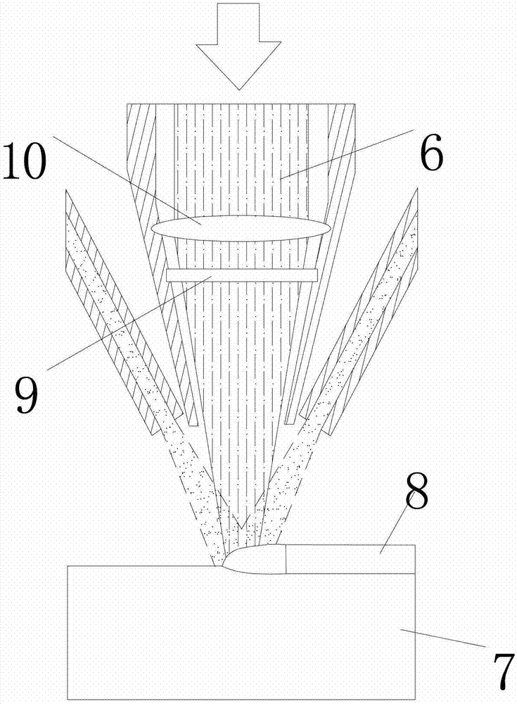
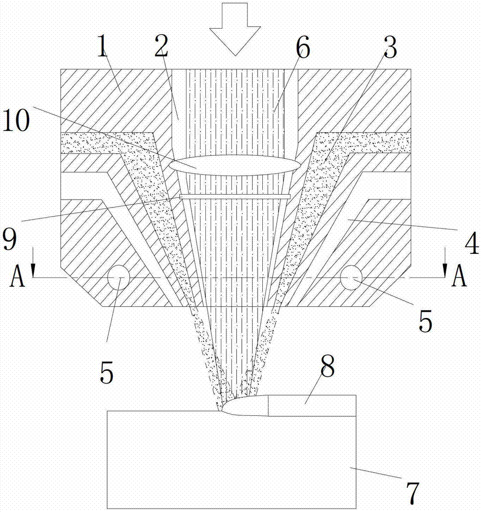
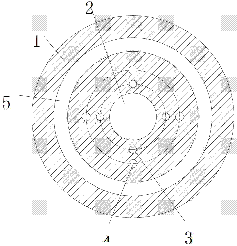
[0023] From attached figure 2 And attached image 3 It can be seen from the schematic diagram of the structure that the present invention provides an internal cooling nozzle for laser cladding, which has a laser channel 2 in the center of the nozzle 1, a powder channel 3 around the laser channel 2, and a The protective gas channel 4 on the periphery of the powder channel 3, and the annular cooling channel 5 opened on the spray head 1 and leading to high-pressure air or liquid. The laser beam 6 enters the laser channel 2 and passes through the focusing lens 10 and the protective lens 9 .

[0024] In this embodiment, there are multiple powder channels 3, which are evenly distributed around the central axis of the laser channel 2, and the extension lines of each powder channel 3 in its length direction meet the central axis of the laser channel 2 below the nozzle 1 at one point. The powder channel 3 can also be an integral channel with the central axis of the laser channe...

Embodiment 2

[0028] as attached Figure 4 As shown, the difference between the internal cooling nozzle for laser cladding in this embodiment and the first embodiment is that there are multiple annular cooling channels 5 . The size and thickness of each annular cooling channel 5 can be set according to the difference of the installation position and the requirement of the cooling effect.

Embodiment 3

[0030] as attached Figure 5 As shown, the difference between the internal cooling nozzle for laser cladding in this embodiment and the first embodiment is that the annular cooling channel 5 is replaced by a spiral cooling channel, and the central axis of the spiral cooling channel is in line with the laser channel 2 coincident with the central axis.

[0031] Since the lower part of the shower head 1 is the place with the highest temperature in the whole shower head, the spiral cooling channel passes through the lower part of the shower head 1 . The position and direction of the spiral cooling channel can be set according to actual needs. It should be noted that the spiral cooling channel cannot communicate with the powder channel 3 and the protective gas channel 4 . The starting end of the spiral cooling channel in this embodiment is located above the powder channel 3 , passing between the powder channel 3 and the shielding gas channel 4 , and the ending end is at the pe...


PUM


Abstract

The invention discloses an inner-cooling nozzle for laser cladding, which comprises a laser channel disposed at the center of the nozzle, a powder channel disposed at the periphery of the laser channel, and an annular cooling channel disposed on the nozzle for high-pressure air or liquid injection; a center axis of the annular cooling channel superposes a center axis of the laser channel. Another technical scheme provided by the invention is that: an inner-cooling nozzle for laser cladding comprises a laser channel disposed at the center of the nozzle, a powder channel disposed at the periphery of the laser channel, and a spiral cooling channel disposed on the nozzle for high-pressure air or liquid injection; a center axis of the spiral cooling channel superposes a center axis of the laser channel. Three coaxial schemes of coaxial powder injection, coaxial protective gas, and coaxial cooling are designed in one laser nozzle, which provides good cladding effect, high efficiency, and more safety and reliability.

Description

technical field [0001] The invention relates to an internal cooling nozzle for laser cladding, belonging to the field of laser cladding. Background technique [0002] Laser cladding is high-energy laser surface cladding. Its physical process is that under the irradiation of high-energy laser beams, the surface of the substrate is rapidly melted, and the liquid metal forms a small-scale molten pool. In this molten pool, the original metal The material is mixed with the added powder to form a new liquid metal layer. After the laser beam passes through, the temperature of the molten pool decreases, the liquid metal cools rapidly, and a new solid cladding layer is formed on the metal surface. Laser cladding can greatly change the metal properties of this key part, such as hardness, wear resistance, heat resistance, corrosion resistance, etc. The coaxial powder feeding method emerged at the beginning of this century, and has achieved great development in recent years, gradually ...

Claims


Application Information

Patent Timeline
IPC IPC(8): C23C24/10
Inventor 柳岸敏张翀昊黄佳欣黄和芳张祖洪
Owner 张家港市和昊激光科技有限公司
Why Eureka
Try Eureka