Eureka AIR delivers breakthrough ideas for toughest innovation challenges, trusted by R&D personnel around the world.

Antenna substrate material using spinel ferrite as matrix and preparation method thereof

A spinel ferrite, antenna substrate technology, applied in the field of composite substrate materials, can solve the problems of poor application effect, large magnetic loss, rising to more than 0.05, etc., and achieves reduction in size and volume, magnetic loss and dielectric loss. The effect of low electrical loss and low loss characteristics

Inactive Publication Date: 2012-12-26
UNIV OF ELECTRONICS SCI & TECH OF CHINA
View PDF3 Cites 5 Cited by
  • Summary
  • Abstract
  • Description
  • Claims
  • Application Information

AI Technical Summary

Problems solved by technology

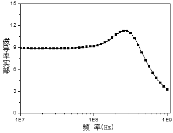
However, the magnetic loss of this material is relatively large. After exceeding 50MHz, the magnetic loss factor will rise to more than 0.05, and it is close to 0.1 at 100MHz, so the application effect above 50MHz is not very good.

Method used


Image

  • Antenna substrate material using spinel ferrite as matrix and preparation method thereof
  • Antenna substrate material using spinel ferrite as matrix and preparation method thereof
  • Antenna substrate material using spinel ferrite as matrix and preparation method thereof

Examples


Embodiment Construction

[0023] The following is a specific embodiment of the antenna substrate material of the present invention.

[0024] The formula molecular formula of the ferrite phase in the composite ceramic material is Mg 0.8 Cu 0.1 Zn 0.05 co 0.05 Fe 1.96 o 4-δ , the molecular formula of zinc silicate is Zn 0.8 SiO 3.8 .

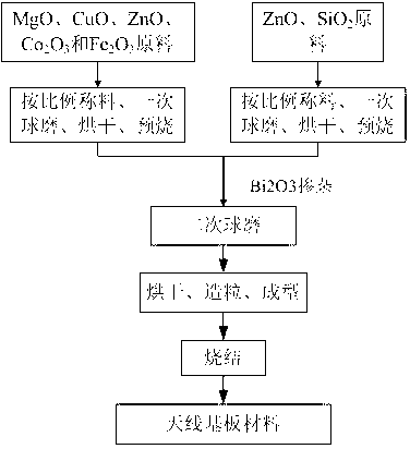
[0025] like figure 1 Shown, the concrete preparation method of this material is as follows:

[0026] Step 1: Fe 2 o 3 , MgO, ZnO, CuO and Co 2 o 3 As the raw material, convert the mass percentage of various oxides according to the ratio of metal elements in the above ferrite formula molecular formula. After accurate weighing, ball mill in a planetary ball mill for 4 hours at a time. After ball milling, the material is placed in an oven at 100 Dry at ℃.

[0027] Step 2: After sieving the dried material obtained in Step 1, compact and drill holes in the sintering bowl, heat up to 900°C for pre-burning at a rate of 3°C / min, keep it warm for 2 hours, and cool dow...


PUM


Abstract

The invention discloses an antenna substrate material using spinel ferrite as a matrix and a preparation method thereof. The antenna substrate material is a composite ceramic material comprising two phases, wherein the main crystal phase is spinel ferrite, and the auxiliary phase is zinc silicate; and the mass percentage of the main crystal phase to the auxiliary phase is 94:6-96:4. The antenna substrate material disclosed by the invention can obviously reduce the dimension and volume of the low-frequency (10-200MHz) microstrip antenna, and ensure the characteristic impedance of the antenna substrate material to be equal or approximate to the characteristic impedance of vacuum, thereby obviously enhancing the radiant efficiency of the antenna.

Description

technical field [0001] The invention belongs to the technical field of electronic materials, and relates to a composite substrate material which is suitable for 10MHz-200MHz low-frequency antenna application and uses spinel ferrite as a matrix. Background technique [0002] In recent years, with the rapid development of wireless communication technology, the miniaturization of communication equipment has become an inevitable development trend. How to reduce the characteristic size of the antenna without affecting its radiation performance has become the current development of miniaturization of wireless communication equipment. The main bottleneck problem faced. According to the design theory of the antenna, the lower the frequency of the antenna application, the larger its characteristic size. Therefore, this bottleneck technical problem is particularly obvious in the antenna used in the low frequency band. We know that using high dielectric material as the antenna substra...

Claims


Application Information

Patent Timeline
IPC IPC(8): C04B35/26C04B35/622
Inventor 荆玉兰苏桦唐晓莉张怀武李元勋钟智勇
Owner UNIV OF ELECTRONICS SCI & TECH OF CHINA
Why Eureka
Eureka Blog
Learn More