Wafer level chip scale package (WLCSP) single chip packaging piece and plastic packaging method thereof
A packaging method and packaging technology, which is applied in the direction of electrical components, electrical solid-state devices, semiconductor devices, etc., can solve the problems of high cost, complicated WLCSP manufacturing process, and extremely high precision requirements for electroplating and photolithography
- Summary
- Abstract
- Description
- Claims
- Application Information
AI Technical Summary
Problems solved by technology
Method used
Image
Examples
Embodiment 1
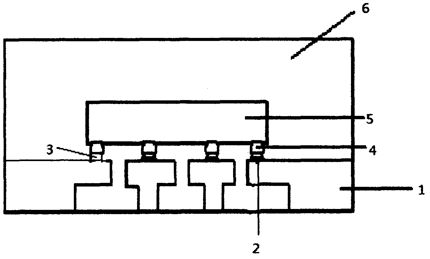
[0037] A WLCSP single-chip package, plated with Au or Cu metal bumps 4 and a tin layer 2, its packaging method: follow the steps below:
[0038] The first step, wafer thinning;
[0039] The thinned thickness of the wafer is 50μm, and the roughness Ra is 0.10mmmm;
[0040] The second step is to plate metal bumps;
[0041] Plating metal bumps 4 on the surface of metal Au in the chip nip area on the entire wafer;
[0042] The third step, scribing;
[0043] For wafers with a thickness below 150 μm, use a double-knife dicing machine and its process;
[0044] The fourth step is to tin-plate the corresponding area of the frame;
[0045] A layer of 2um tin layer 2 is plated on the corresponding area of the PAD on the pin 1 in the frame;
[0046] The fifth step, core;
[0047] Turn the IC chip 5 upside down, and weld the metal bumps 4 on the IC chip 5 to the frame by using the Flip-Chip process;
[0048] The sixth step, reflow soldering;
[0049] Using the reflow soldering ...
Embodiment 2
[0053] A WLCSP single-chip package, coated with Cu metal bumps 4 and tin layer 2, its packaging method: follow the steps below:
[0054] The first step, wafer thinning;
[0055] The thickness of wafer thinning is 130μm, and the roughness Ra is 0.20mm;
[0056] The second step is to plate metal bumps;
[0057] Plating metal bumps 4 on the metal Cu surface of the chip nip area on the entire wafer;
[0058] The third step, scribing;
[0059] For wafers with a thickness below 150 μm, use a double-knife dicing machine and its process;
[0060] The fourth step is to tin-plate the corresponding area of the frame;
[0061] A layer of 25um tin layer 2 is plated on the corresponding area of PAD on pin 1 in the frame;
[0062] The fifth step, core;
[0063]Turn the IC chip 5 upside down, and weld the metal bumps 4 on the IC chip 5 to the frame by using the Flip-Chip process;
[0064] The sixth step, reflow soldering;
[0065] Using the reflow soldering process after SMT, afte...
Embodiment 3
[0069] A WLCSP single-chip package, plated with Au or Cu metal bumps 4 and a tin layer 2, its packaging method: follow the steps below:
[0070] The first step, wafer thinning;
[0071] The thickness of wafer thinning is 200μm, and the roughness Ra is 0.30mm;
[0072] The second step is to plate metal bumps;
[0073] Plating metal bumps 4 on the surface of metal Al or Cu in the chip nip area on the entire wafer;
[0074] The third step, scribing;
[0075] Wafers above 150μm adopt ordinary dicing process;
[0076] The fourth step is to tin-plate the corresponding area of the frame;
[0077] A layer of 50um tin layer 2 is plated on the corresponding area of PAD on pin 1 in the frame;
[0078] The fifth step, core;
[0079] Turn the IC chip 5 upside down, and weld the metal bumps 4 on the IC chip 5 to the frame by using the Flip-Chip process;
[0080] The sixth step, reflow soldering;
[0081] Using the reflow soldering process after SMT, after tin melting treatment, ...
PUM
 Abstract
Description
Claims
Application Information
 - R&D
- Intellectual Property
- Life Sciences
- Materials
- Tech Scout
- Unparalleled Data Quality
- Higher Quality Content
- 60% Fewer Hallucinations
Browse by: Latest US Patents, China's latest patents, Technical Efficacy Thesaurus, Application Domain, Technology Topic, Popular Technical Reports.
© 2025 PatSnap. All rights reserved.Legal|Privacy policy|Modern Slavery Act Transparency Statement|Sitemap|About US| Contact US: help@patsnap.com

