Check patentability & draft patents in minutes with Patsnap Eureka AI!

Active power factor correction (PFC) control circuit based on complex programmable logic device (CPLD)

A technology for controlling circuits and converting circuits, which is applied in the fields of electrical components, energy industry, sustainable manufacturing/processing, etc. It can solve problems such as the contradiction between sampling frequency and switching frequency, difficulty in setting PI parameters, sensitive circuit parameters, etc., and achieve robustness Good results

Active Publication Date: 2012-12-26
FOSHAN BAYKEE NEW ENERGY TECH INC
View PDF4 Cites 4 Cited by
  • Summary
  • Abstract
  • Description
  • Claims
  • Application Information

AI Technical Summary

Problems solved by technology

[0006] However, there are also some disadvantages in pure DSP software control, such as the contradiction between sampling frequency and switching frequency, control delay that always lags behind a switching beat, complex mathematical modeling and algorithm design, and high operating speed of DSP. Requirements, difficulty in setting PI parameters, sensitivity to circuit parameters, etc.

Method used


Image

  • Active power factor correction (PFC) control circuit based on complex programmable logic device (CPLD)
  • Active power factor correction (PFC) control circuit based on complex programmable logic device (CPLD)
  • Active power factor correction (PFC) control circuit based on complex programmable logic device (CPLD)

Examples


Embodiment Construction

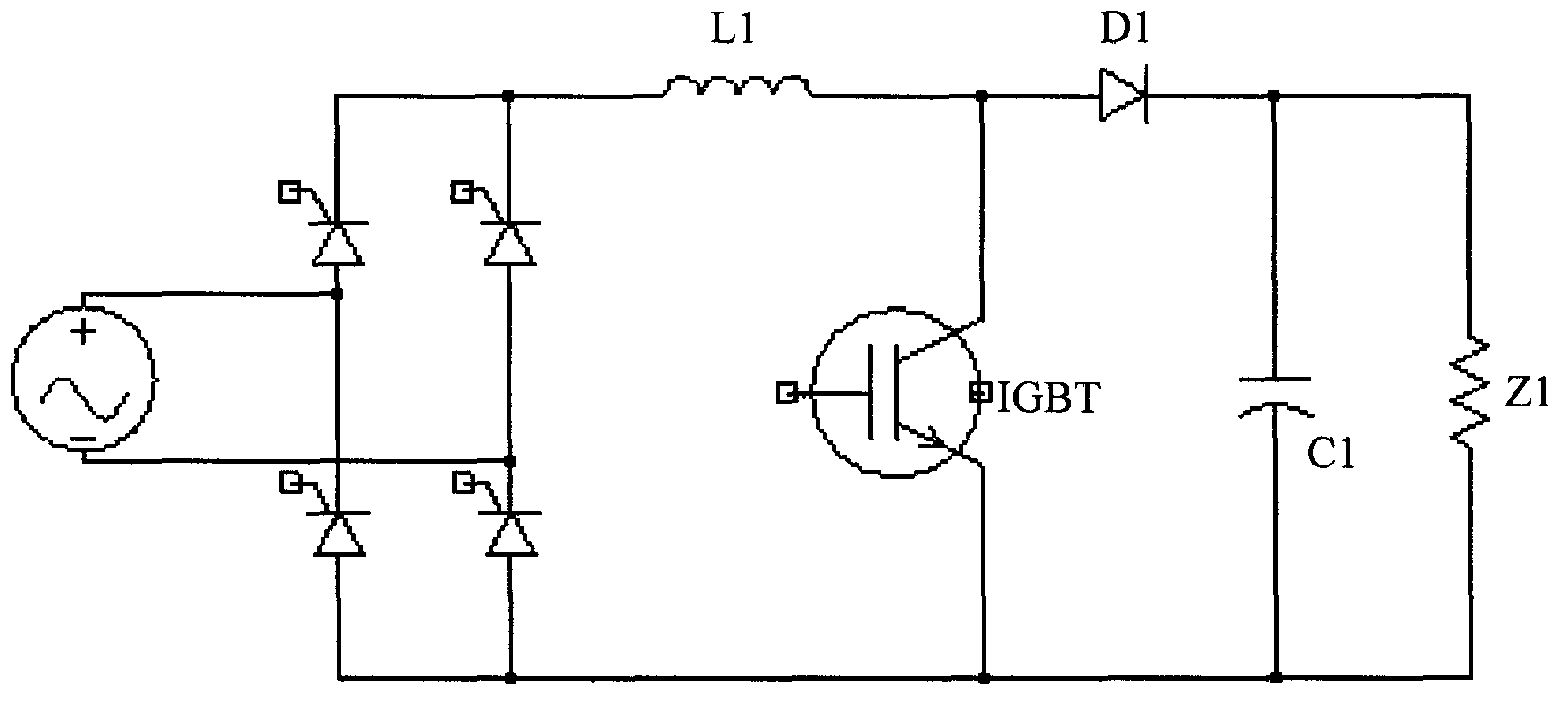
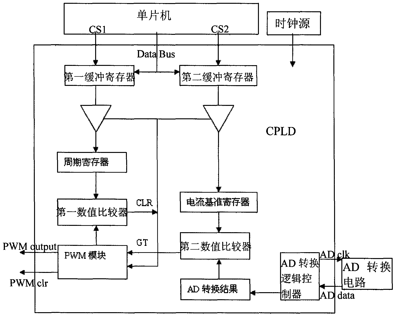
[0021] Such as image 3 A CPLD-based active PFC control circuit is shown, which includes a CPLD, a single-chip microcomputer, an AD conversion circuit, a clock source, and a current sampling circuit for current sampling of an inductor in a BOOST-type PFC circuit topology. The CPLD includes the first A buffer register, a second buffer register, a period register, a first numerical comparator, a second numerical comparator, a current reference register, a PWM module capable of generating a triangular wave reference, and an AD conversion circuit for controlling AD conversion and storing AD conversion results The AD conversion logic controller, the first buffer register is connected with the period register and the first numerical comparator PWM module in turn, the second buffer register is connected with the current reference register, the second numerical comparator, and the AD conversion logic controller in turn, and the single-chip microcomputer has The corresponding data comm...


PUM


Abstract

The invention discloses an active power factor correction (PFC) control circuit based on a complex programmable logic device (CPLD). The active PFC control circuit based on the CPLD comprises a CPLD, a single chip circuit, an analog digital (AD) conversion circuit, a clock source, a current sampling circuit which is used to sample current for inductance in BOOST type PFC circuit topological structure, the CPLD is composed of a first buffer register, a second buffer register, a period register, a first numeric comparator, a second numeric comparator, a current reference register, a pulse width modulation (PWM) module, and an AD conversion logic controller, the clock source is connected into a clock signal input terminal of the CPLD, the AD conversion circuit is communicated with the AD conversion logic controller, and the current sampling circuit is connected with the AD conversion circuit. The first numeric comparator and the second numeric comparator are combined to control the PWM pulse width and the PWM pulse is output by the PWM module, and then the PWM pulse is used to control switching of an insulated gate bipolar translator (IGBT) of the BOOST type PFC circuit topological structure so that actual inductive current of the BOOST type PFC circuit topological structure changes with a reference value of inductive current. The active PFC control circuit based on the CPLD is high in the requirement for an external central processing unit (CPU), degree of harmonic distortion of an input current is extremely small, and controlled robustness is good.

Description

technical field [0001] The invention relates to a power factor correction circuit, in particular to a CPLD-based active PFC control circuit. Background technique [0002] The rapid development of electronic technology and power electronic technology, and the use of a large number of power electronic equipment have brought increasingly serious harmonic and reactive power hazards to the power grid. Power factor correction (PFC) technology is generally used in uninterruptible power supply (UPS) to solve the problem of harmonic pollution, such as figure 1 The shown BOOST type PFC circuit topology is mainly composed of inductor L1, IGBT tube, diode D1, capacitor C1, resistor Z1 and rectifier bridge. [0003] Traditional active PFC circuits are implemented by integrated analog control chips, such as UC3854, L4981A / B, etc., but the analog control chips themselves have some defects, such as components are prone to aging and thermal drift; the control method is not flexible, and the...

Claims


Application Information

Patent Timeline
IPC IPC(8): H02M1/42
CPCY02B70/126Y02B70/10Y02P80/10
Inventor 黄敏潘世高
Owner FOSHAN BAYKEE NEW ENERGY TECH INC
Features
  • R&D
  • Intellectual Property
  • Life Sciences
  • Materials
  • Tech Scout
  • Unparalleled Data Quality
  • Higher Quality Content
  • 60% Fewer Hallucinations
Learn More