
Light-emitting device and method for manufacturing the same

A technology for light-emitting devices and light-emitting bodies, which can be applied to electrical components, circuits, semiconductor devices, etc., can solve problems such as poor low-temperature characteristics, poor productivity, and deterioration, and achieve the effects of excellent low-temperature characteristics, less internal damage, and excellent weather resistance.

Inactive Publication Date: 2013-01-02
SHIN ETSU CHEM IND CO LTD
View PDF5 Cites 2 Cited by
  • Summary
  • Abstract
  • Description
  • Claims
  • Application Information

AI Technical Summary

Problems solved by technology

Although it varies depending on the usage environment, it may take time to install a protective structure separately.
[0004] In order to prevent these situations from happening, there is a proposal to cover a flexible substrate on which a light-emitting element has been placed with a silicone tube, so that the flexible substrate can be used in various environments, but In the proposal, there is no detailed description of which silicone is used (Patent Document 4 below)
[0005] As in Patent Document 4, the structure covered with a tube is simple, but because there is a space (gap) between the tube and the illuminant, there is a possibility that moisture such as water vapor and rainwater will be mixed in, which may cause Possibility of internal electrical damage
In addition, optically, since birefringence and reflection repeatedly occur in space, it is not desirable to create space in terms of transparency and light transmission, and there is also a problem that the interior will become foggy due to moisture.
When the product is cut short, it is sometimes difficult to cut the tube smoothly, and when the tube is longer than 5m, it is difficult to seal the luminous body in the tube, and the efficiency is extremely poor, and the productivity is poor.
[0006] In Patent Document 4, it is also described that the flexible substrate on which the light-emitting components are arranged is enclosed in urethane (urethane), but urethane is not the most suitable material because it tends to turn yellow and change the transmittance. Low-temperature characteristics are also poor, so when used in a severe low-temperature environment, it will lose flexibility and deteriorate

Method used

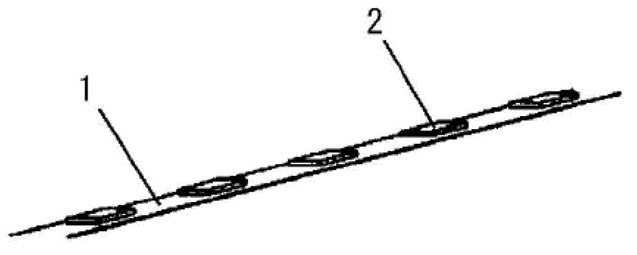
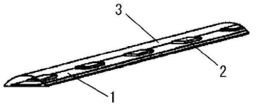
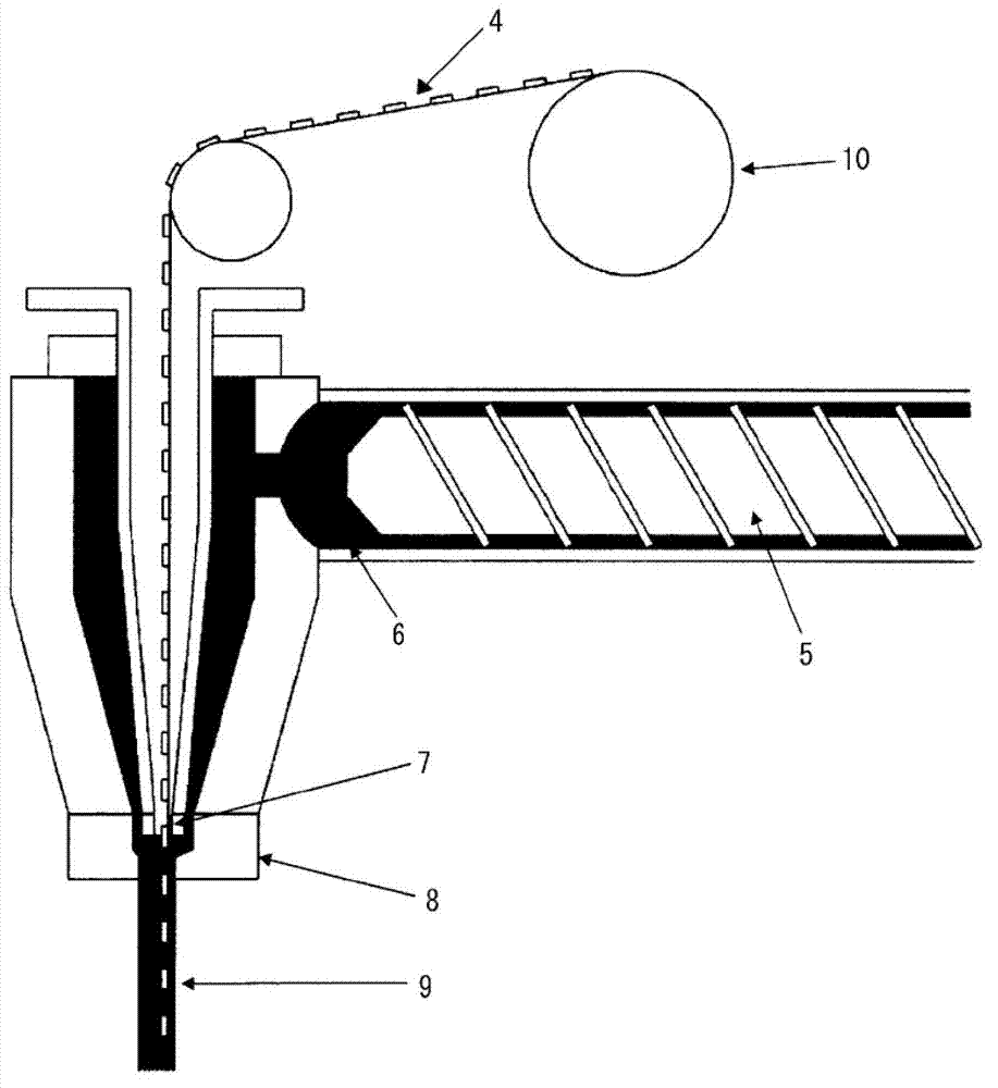

Image

  • Light-emitting device and method for manufacturing the same
  • Light-emitting device and method for manufacturing the same
  • Light-emitting device and method for manufacturing the same

Examples


Embodiment 1

[0082] Using a kneader, 100 parts by mass of the above (a-1), 15 parts by mass of the above (c-1), and 4.5 parts by mass of the surface treatment (c-1) were prepared while heating at 170°C for 2 hours The above-mentioned (f-1) of the agent and 1 mass part of ion-exchanged water were kneaded uniformly to prepare an unvulcanized silicone compound A.

[0083] Using twin rollers, 100 parts by mass of unvulcanized silicone compound A, 0.2 parts by mass of vinyl siloxane complex of chloroplatinic acid (b-1), 0.7 parts by mass of curing agent (b-2 ) and 0.2 parts by mass of vinylcyclohexanol as a control agent of (b-1) were kneaded to obtain a silicone composition A.

[0084] by image 3 In the manner shown, the silicone composition A and the core material formed by connecting multiple LED components to the flexible circuit board are inserted simultaneously from different insertion ports, and extrusion molding is performed at a speed of 1m / min. , and then, it was cured at 130° C. f...

Embodiment 2

[0086] Except that in 100 parts by mass of the silicone composition A of Example 1, 3 parts by mass of titanium oxide (color tone adjusting agent) with an average particle diameter of 3 μm was further prepared to make the silicone composition B, the rest were the same as the implementation Example 1 was carried out in the same manner to obtain a molded product. The obtained molded article was evaluated as follows.

Embodiment 3

[0088] Using a kneader, while heating at 170°C for 2 hours, 100 parts by mass of the above (a-2), 10 parts by mass of the above (c-1), and 4.5 parts by mass of the surface treatment as (c-1) were prepared The above-mentioned (f-1) of the agent and 1 mass part of ion-exchanged water were kneaded uniformly to prepare an unvulcanized silicone compound B.

[0089] A molding was obtained in the same manner as in Example 2 except that the unvulcanized silicone compound B was used instead of the unvulcanized silicone compound A. The obtained molded article was evaluated as follows.


PUM

PropertyMeasurementUnit
Lengthaaaaaaaaaa
Thicknessaaaaaaaaaa
Widthaaaaaaaaaa

Abstract

Disclosed is a light-emitting device in which a core comprising a wiring body provided with a light-emitting element is tightly enclosed within silicone rubber. The core is extruded from a die while the periphery thereof is surrounded by a curable silicone rubber composition, and the core can then be tightly enclosed by curing the curable silicone rubber composition. It is therefore possible to increase the weather resistance of the light-emitting device.

Description

technical field [0001] The present invention relates to a light-emitting device and a method of manufacturing the light-emitting device. The light-emitting device can be used for outdoor lighting and decoration because of its excellent weather resistance. The method of manufacturing the light-emitting device can be shaped into a long strip. Background technique [0002] So far, cable-shaped or tape-shaped LED (light-emitting diode, light-emitting diode) circuit bodies have been proposed for decoration and outdoor lighting (Patent Documents 1 to 3 below). Since these circuit bodies do not have the function of protecting the board, they are limited by the installation environment. [0003] That is, the following limitations: limited by physical factors such as external stress, shock, and vibration; limited by chemical factors such as moisture and rain, cleaning agents, harmful gases, and ultraviolet rays; and limited by mold and insect adhesion, etc. limited by biological fac...

Claims


Application Information

Patent Timeline
IPC IPC(8): H01L33/56C08L83/05C08L83/07
CPCC08K3/36H01L2933/005C08G77/20C08G77/12C08L83/04H01L33/56C08L83/00
Inventor 畔地秀一大泽康久山口久治茂木正弘
Owner SHIN ETSU CHEM IND CO LTD
Learn More