Rotary floating cutting numerical control machine tool for silicon rod

A CNC machine tool and floating cutting technology, applied in the field of CNC machine tools, can solve the problems of delayed production, difficulty in cutting finished products, and rising production costs, and achieve the effects of reducing production costs, cutting time, and improving production efficiency.

Inactive Publication Date: 2013-01-09
刘鸿彬
View PDF9 Cites 23 Cited by
  • Summary
  • Abstract
  • Description
  • Claims
  • Application Information

AI Technical Summary

Problems solved by technology

For this kind of silicon rod to be cut, when the old-fashioned CNC cutting machine is used to position the silicon rod with single-point forced pressure, and the cutter head tool is used for radial full-diameter cutting, the silicon rod itself is subject to great vibration, and the cutting direction cannot be in line with the silicon rod. The axis of the rod bending remains vertical, the cut part is easily broken, and it is difficult to cut out the finished product
This traditional cutting process and equipment not only caused great economic losses, but also delayed the production of the next process, which greatly increased the production cost of the enterprise.

Method used


Image

  • Rotary floating cutting numerical control machine tool for silicon rod
  • Rotary floating cutting numerical control machine tool for silicon rod
  • Rotary floating cutting numerical control machine tool for silicon rod

Examples


Embodiment 1

[0042] A silicon rod rotary floating cutting CNC machine tool, including a numerical control box, a bed, a transmission mechanism, a cutting mechanism arranged on the bed, and a silicon rod clamping mechanism, is characterized in that: the silicon rod clamping mechanism includes a vertically coordinated The active rotating supporting wheel 8 and the floating rotating pressing wheel 11 holding the silicon rod 10; Non-concentric axial rotation on the horizontal position of the supporting wheel 9

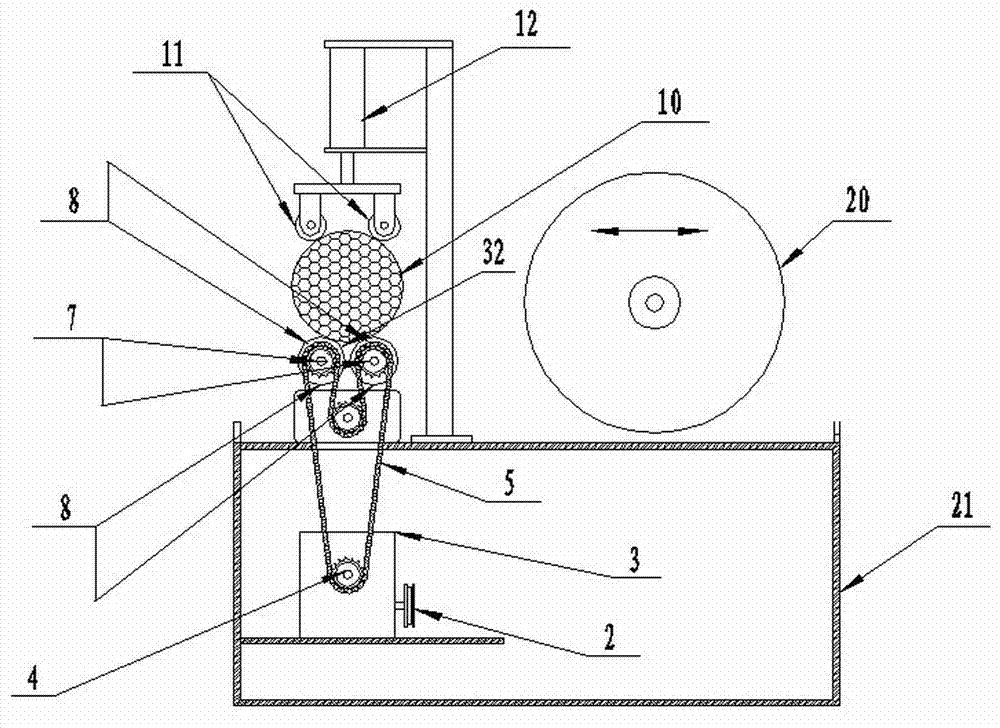
[0043] The floating rotary pressing wheel 11 is vertically located above the silicon rod 10 and is connected to the elastic extruding device 12, which drives the floating rotating pressing wheel 11 to press the silicon rod 10 tightly around the shape of the outer circle of the silicon rod.

[0044] The active rotating support roller 8 is located below the silicon rod 10 and is connected with the transmission mechanism, and the transmission mechanism drives the silicon rod 10 to rotate ...

Embodiment 2

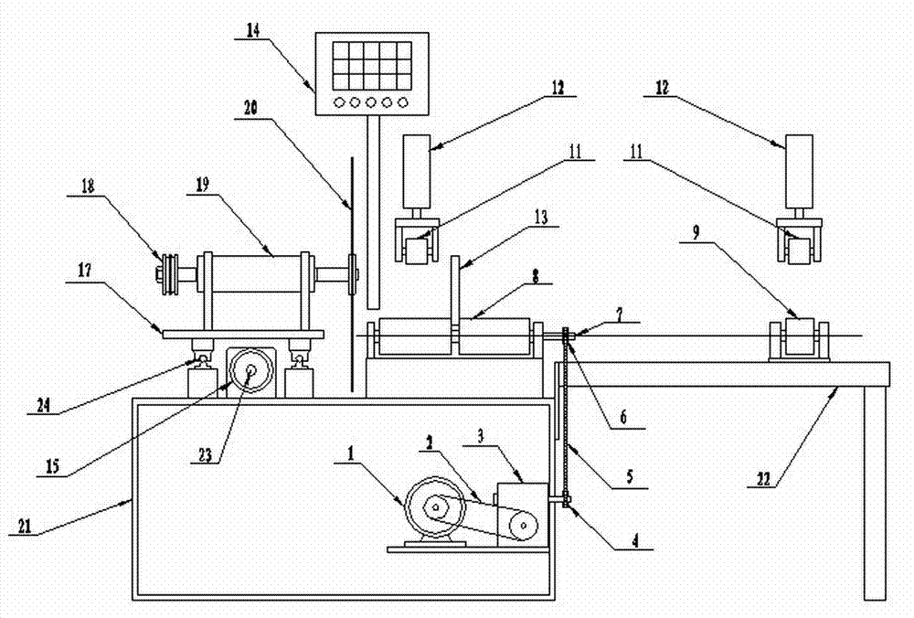
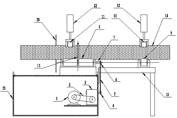
[0052] Such as figure 1 , figure 2 As shown, a silicon rod rotary floating cutting numerical control machine tool includes a numerical control box 14, a bed 21, a transmission mechanism, a cutting mechanism and a silicon rod clamping mechanism are respectively arranged on the bed, and the silicon rod clamping mechanism includes a vertically coordinated The active rotating support roller 8 and the floating rotating pressure wheel 11 holding the silicon rod 10; the floating rotating pressure wheel is connected to the floating cylinder, and the gas of the floating cylinder 12 drives the drive shaft of the cylinder, and the cylinder drive shaft is connected to the floating rotating pressure wheel 11 to open the floating cylinder 12 , the cylinder drive shaft drives the floating rotating pressure wheel 11 to tightly press the outer circle of the silicon rod 10, and the floating rotating pressure wheel 11 moves up and down with the fluctuation of the outer circle of the silicon ro...

Embodiment 3

[0065] In the same way, the elastic extruding device 12 is a spring compression device, and the spring compression device ( Figure 7 ) is equipped with a spring 29 connected to a driving shaft 30, the other end of the driving shaft 30 is connected to a cross bar 31, and the two ends of the cross bar 31 are respectively connected to the floating rotating pressure wheel 11, and the spring 29 drives the driving shaft 30 to press down, driving the cross bar 31 to two The floating rotating pressure wheel (11) at the end surrounds the shape of the outer circle of the silicon rod and presses the outer circle of the silicon rod 10 in good time.

[0066] The active rotating supporting roller 8 is coaxially provided with two groups, and a positioning groove 32 is formed between the two groups; the silicon rod 10 is covered with a cutting and measuring ring 13, and the cutting and measuring ring 13 is located in the positioning groove. The cutting ring 13 rotates with the silicon rod 10...


PUM


Abstract

The invention discloses a rotary floating cutting numerical control machine tool for a silicon rod, and relates to a numerical control machine tool, in particular to a numerical control cutting machine for cutting the silicon rod. The rotary floating cutting numerical control machine tool comprises a numerical control box, a machine tool body, a transmission mechanism, and a cutting mechanism and a silicon rod clamping mechanism which are arranged on the machine tool body, and is characterized in that the silicon rod clamping mechanism comprises a driving rotation support wheel which clamps the silicon rod in a matching manner in the vertical direction, and a floating rotary pressing wheel; the floating rotary pressing wheel is connected with an elastic pressing device which drives the floating rotary pressing wheel to tightly press the silicon rod; and the transmission mechanism is connected with a shaft of the driving rotation support wheel. The rotary floating cutting numerical control machine tool can realize the non-concentric axial rotation floating radius cutting of polycrystalline silicon rods which have the characteristics that the material texture density is sparse, workpieces are bent in the axial direction, ovality exists in the diameter direction, the diameters are different, the appearances are not irregular, the breaking phenomenon is easy to generate, and the like in the floating rotation state, and is novel and capable of realizing the automatic radius cutting.

Description

technical field [0001] The invention relates to a numerical control machine tool, in particular to a numerical control cutting machine for cutting silicon rods. Background technique [0002] At present, in the domestic polysilicon industry manufacturers, it is necessary to cut the restored silicon rods with a diameter of 2-8 inches radially to length for finished product inspection and to meet the production needs of different next processes. [0003] The patent number is 200920287130.2, and the Chinese patent "single / polycrystalline silicon rod cutting machine" with a publication date of 2010.12.22 discloses a silicon rod cutting machine, which includes a crystal rod fixing device, a cutting system and a cooling system. The crystal rod The fixing device includes a number of fixed clamping devices, which are arranged on the workbench, and the fixed clamping devices are respectively arranged on the left and right sides of the grinding wheel. In addition, the workbench is prov...

Claims


Application Information

Patent Timeline
Patent Type & Authority Applications(China)
IPC IPC(8): B28D5/02B28D7/00B28D7/04
Inventor 刘鸿彬
Owner 刘鸿彬
Why Eureka
Try Eureka