
Microfluidic cell culture chip and real-time observation system thereof

A cell culture and microfluidic technology, applied in tissue cell/virus culture devices, enzymology/microbiology devices, biomass post-processing, etc. Depletion and other issues, to achieve the effect of easy to carry observation, low processing cost and requirements, and avoid splashing

Inactive Publication Date: 2013-01-09
CHONGQING UNIV
View PDF4 Cites 17 Cited by
  • Summary
  • Abstract
  • Description
  • Claims
  • Application Information

AI Technical Summary

Problems solved by technology

[0007] 2) It is impossible to observe the growth of cells in real time. The current common cell observation method needs to take the cell culture bottle out of the constant temperature incubator. This is feasible for short-term observation, but not for the situation that requires real-time observation. Be applicable
[0008] 3) Due to the large volume of the incubator, it is not suitable for the trend of miniaturization. At the same time, it needs to maintain a constant temperature and consume a lot of energy, and it needs more nutrients to fill
In addition, due to the large volume of the culture bottle and the inability to update the culture medium in real time, there may be problems of incomplete utilization of the culture medium or depletion of nutrients in local areas

Method used


Image

  • Microfluidic cell culture chip and real-time observation system thereof
  • Microfluidic cell culture chip and real-time observation system thereof

Examples


Embodiment Construction

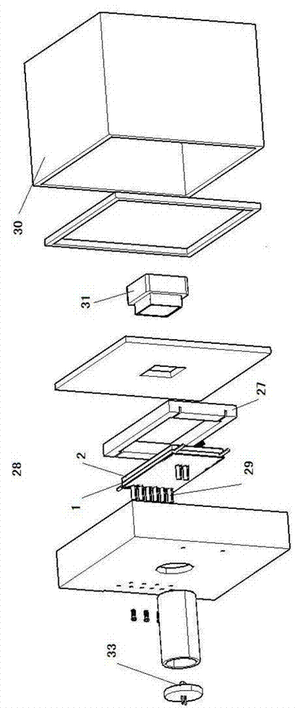
[0034] The specific implementation manners of the present invention will be described in detail below in conjunction with the accompanying drawings.

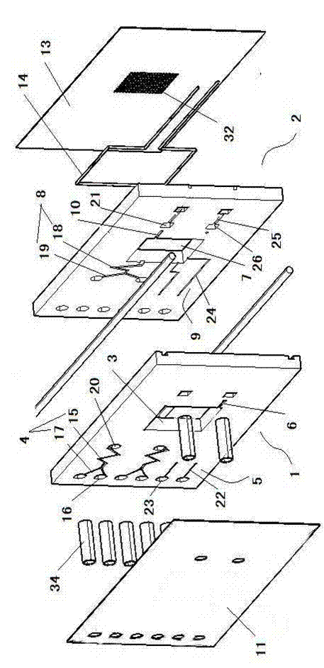
[0035] Such as figure 1 Shown is a schematic structural diagram of an embodiment of the microfluidic cell culture chip of the present invention, which is an exploded view of the microfluidic cell culture chip.

[0036] The microfluidic cell culture chip of this embodiment includes an upper chip 1 and a lower chip 2 .

[0037] The upper layer chip 1 is provided with the first through hole 3 as the upper gas storage chamber of the cell culture chamber, and the upper surface of the upper layer chip 1 is provided with the first liquid channel 4 for injecting the cell culture fluid into the cell culture chamber, for injecting the cell culture fluid into the cell culture chamber. The culture chamber injects a first gas channel 5 for cell culture sterile gas and a first exhaust channel 6 for exhausting exhaust gas, and the first exhaust...


PUM

PropertyMeasurementUnit
thicknessaaaaaaaaaa

Abstract

A microfluidic cell culture chip comprises an upper chip and a lower chip. The upper chip is provided with a first through hole, a first fluid passage, a first gas passage and a first exhaust passage are arranged on the upper surface of the upper chip, wherein the first exhaust passage is communicated with the first through hole. The lower chip is provided with a second through hole, and a second fluid passage, a second gas passage and a waste fluid passage which are communicated with the second through hole are arranged on the upper surface of the lower chip. The first fluid passage and the second fluid passage are communicated, the first gas passage and the second gas passage are communicated, an upper film layer is covered on the upper surface of the upper chip, a bottom layer sealing structure is arranged on the lower surface of the lower chip, the upper chip and the lower chip are pressed to be fit, a heating device is arranged between the lower surface of the lower chip and the bottom layer sealing structure, and the upper film layer, the first through hole, the second through hole and the bottom layer sealing structure surrounds to form a cell culturing cavity. The invention further discloses a real-time observation system of the microfluidic cell culture chip.

Description

technical field [0001] The invention relates to a culture device for culturing cells, in particular to a microfluidic cell culture chip and a microfluidic cell culture chip real-time observation system for real-time observation of the microfluidic cell culture chip. Background technique [0002] The culture methods are slightly different according to the different cell types, but the general steps have certain commonality. It is mainly divided into primary culture and subculture. After years of development and improvement, the general method of cell culture is as follows. [0003] Primary culture is first to take part of the tissue to be isolated from the organism, and use enzyme digestion to digest the extracellular matrix, and then disperse the tissue into single cells. Undigested tissue pieces are removed by filtration to obtain a single cell suspension containing isolated cells. Centrifuge the filtered liquid at a low speed for about 5-6 minutes, remove the supernatan...

Claims


Application Information

Patent Timeline
Patent Type & Authority Applications(China)
IPC IPC(8): C12M3/00C12M1/04
Inventor 罗洪艳廖彦剑胡宁郑飞侯文生罗庆张雨雯陈礼
Owner CHONGQING UNIV
Learn More