Large view field optical imaging system based on computing imaging technology

An optical imaging system and computational imaging technology, applied in the field of aerospace optical remote sensors, can solve problems such as resolution discount, system stray light, system real-time performance reduction, etc., to achieve easy processing and assembly, resolution, and consistent resolution Effect

Active Publication Date: 2014-08-27
BEIJING RES INST OF SPATIAL MECHANICAL & ELECTRICAL TECH
View PDF5 Cites 2 Cited by
  • Summary
  • Abstract
  • Description
  • Claims
  • Application Information

AI Technical Summary

Problems solved by technology

However, they all have their own shortcomings. The high-resolution scanning imaging of the small field of view must have a complex scanning mechanism, which directly leads to the reduction of the real-time performance of the system and greatly reduces the reliability of the system; although the fisheye lens can achieve more than 180 ° large field of view imaging, but there is a large distortion in the peripheral field of view, the illumination of the peripheral field of view is low, and the entire image surface cannot form a consistent resolution; the ring-shaped staring imaging system surrounds the 360° range of the optical axis of the optical system The cylindrical field of view is projected into an annular area on a two-dimensional plane. Although it can realize the panoramic real-time imaging of the 360° annular space, it can only image the annular field of view. There is a central blind spot in the imaging system, and the stray light of the system Seriously, the resolution is greatly reduced

Method used


Image

  • Large view field optical imaging system based on computing imaging technology
  • Large view field optical imaging system based on computing imaging technology
  • Large view field optical imaging system based on computing imaging technology

Examples


Embodiment Construction

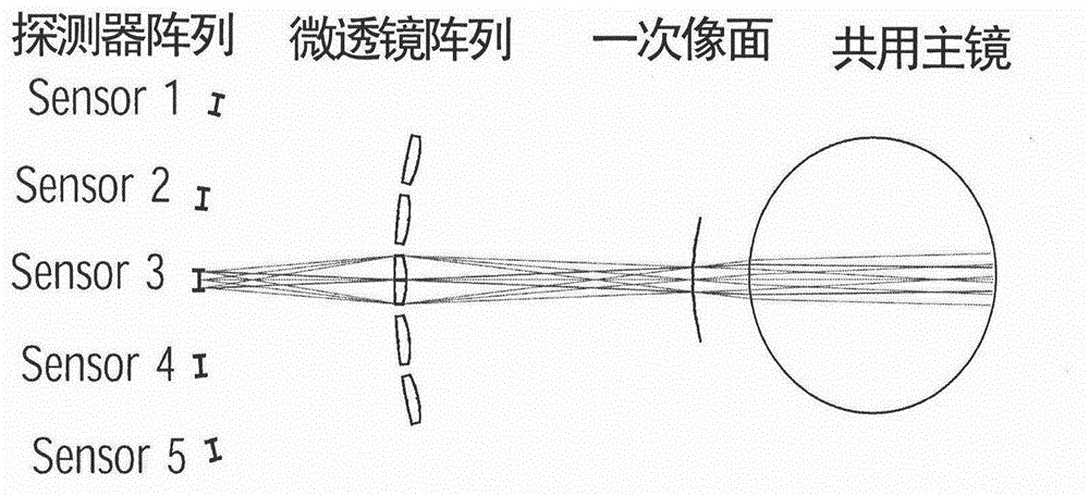
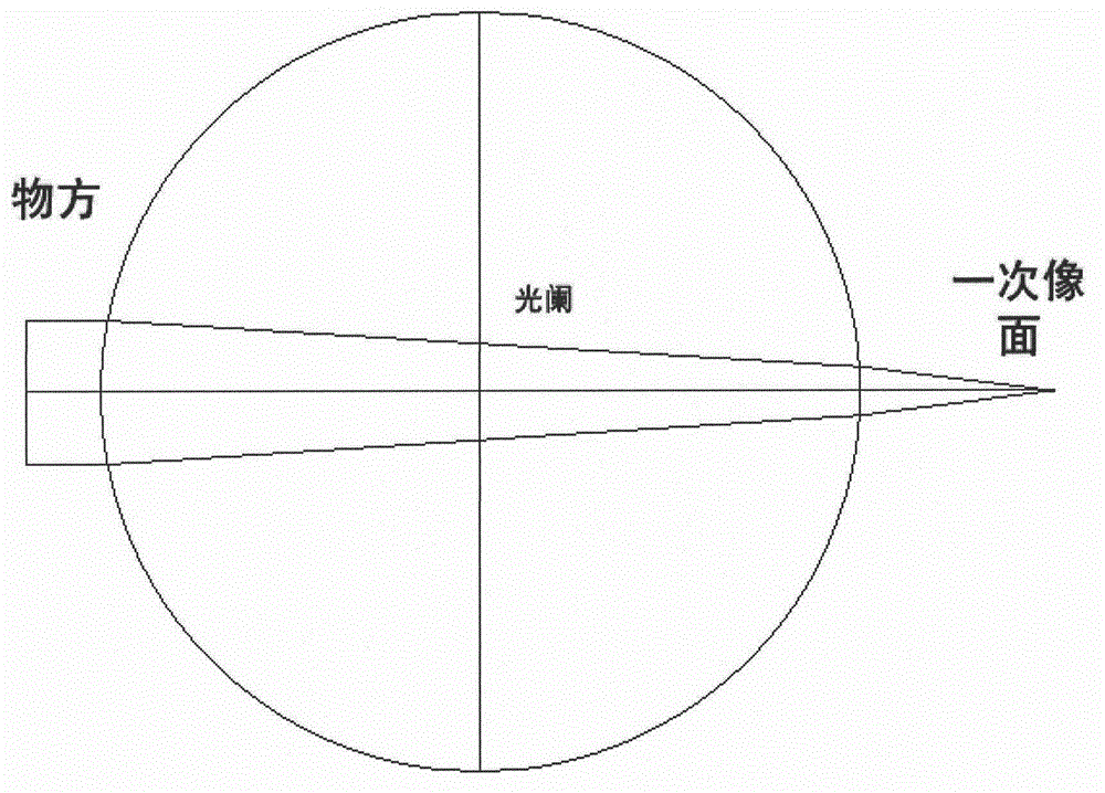
[0019] Such as figure 1 As shown, the large field of view optical imaging system based on the computational imaging technology of the present invention includes a common primary mirror, a microlens array and a detector array. The shared primary mirror is a monocentric spherical mirror, which is composed of two hemispherical mirrors, and the aperture is located in the middle of the two hemispherical mirrors. Such as Figure 2a shown. The light rays of different fields of view enter the common primary mirror from the object side of the optical system, and the common primary mirror performs an imaging; a microlens array corresponding to the detector array is introduced behind the primary image surface of the common primary mirror, and each microlens on the microlens array is exactly the same , the light emitted from the primary image plane is imaged twice by the microlens array, then arrives at the detector array and is finally imaged; the detectors on the detector array are al...


PUM


Abstract

Provided is a large view field optical imaging system based on a computing imaging technology. An imaging system structure of a shared primary mirror, a micro lens array and a detector array is adopted. Incident light respectively passes through the shared primary mirror and the micro lens array and finally reaches the detector array to perform imaging, image restoration (removing influence of spherical aberration on image quality) is performed on each subimage through the computing imaging technology, and a whole clear image can be obtained after registering compositing is performed on each subimage. The shared primary mirror is a single core sphere mirror composed of two semisphere mirrors. The whole optical imaging system is simple in structure, fully symmetrical and easy to process, install and test, has the advantages of extra large view field and low structural complexity and the like, and is particularly suitable for large-range search of space targets and stratosphere air surveillance and the like.

Description

technical field [0001] The invention belongs to the technical field of aerospace optical remote sensors, and relates to a large field of view optical imaging system based on computational imaging technology with a large field of view and low structural complexity. Background technique [0002] With the continuous improvement of human beings' ability to enter space and use space, the impact of space on national strategic interests has become increasingly prominent. Human beings have gone through the stage of entering space-utilizing space-monitoring space, and are entering the era of controlling space. With the development of modern tactical warfare, the demand for high-resolution, large-field-of-view stratospheric air surveillance systems and space-based large-scale target search systems is becoming more and more urgent. However, traditional large-field-of-view systems can no longer meet such requirements. Require. [0003] Traditional large field of view optical systems m...

Claims


Application Information

Patent Timeline
Patent Type & Authority Patents(China)
IPC IPC(8): G02B13/00G02B13/06
Inventor 戚均恺周峰汤天瑾庄绪霞阮宁娟贺金平李岩胡博
Owner BEIJING RES INST OF SPATIAL MECHANICAL & ELECTRICAL TECH
Why Eureka
Try Eureka