
Combined adjustable transformer bobbin and transformer applying same

A transformer skeleton, combined technology, applied in transformer/inductor parts, transformer/inductor coil/winding/connection, electrical components, etc., can solve the problem of reducing the overall volume of the transformer, increasing the material cost, and reducing the circuit board. The problem of layout space and other issues can reduce the difficulty of production process, save manufacturing cost and save layout space.

Active Publication Date: 2013-01-09
MORNSUN GUANGZHOU SCI & TECH
View PDF5 Cites 19 Cited by
  • Summary
  • Abstract
  • Description
  • Claims
  • Application Information

AI Technical Summary

Problems solved by technology

The general measures for the existing transformer skeleton to meet the safety distance are to directly increase the distance between the primary coil slot and the secondary coil slot of the transformer skeleton, and to supplement the protection with insulating materials such as retaining walls, tapes, and Teflon bushings. The measures not only increase the volume of the transformer skeleton, but also increase the cost of materials, and are not conducive to reducing the overall volume of the transformer, and are also not conducive to reducing the layout space of the circuit board; another common existing method is to place the secondary of the transformer The winding is led out by three-layer insulated wire and suspended to form flying wires, and the necessary distance is met through the flying wire welding holes on the circuit board. The defects of this transformer are: the process control of flying wires is difficult, and the upper Board installation is difficult to operate, not only has high requirements on the professional skills of operators, but also takes a long time to operate, resulting in increased manufacturing costs

Method used


Image

  • Combined adjustable transformer bobbin and transformer applying same
  • Combined adjustable transformer bobbin and transformer applying same
  • Combined adjustable transformer bobbin and transformer applying same

Examples


Embodiment Construction

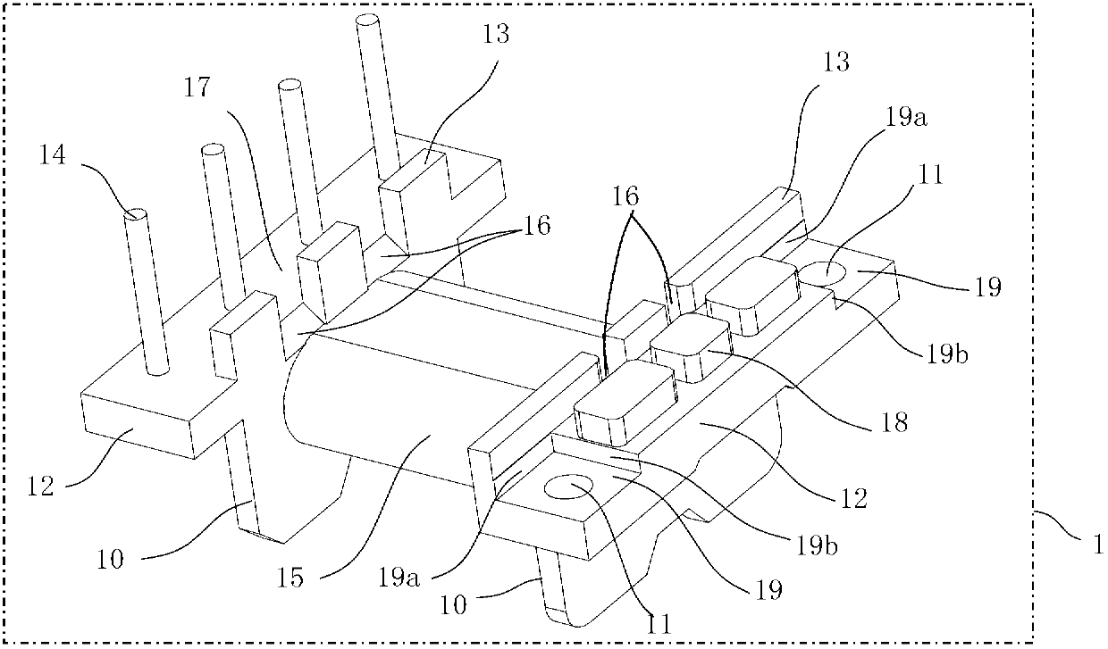
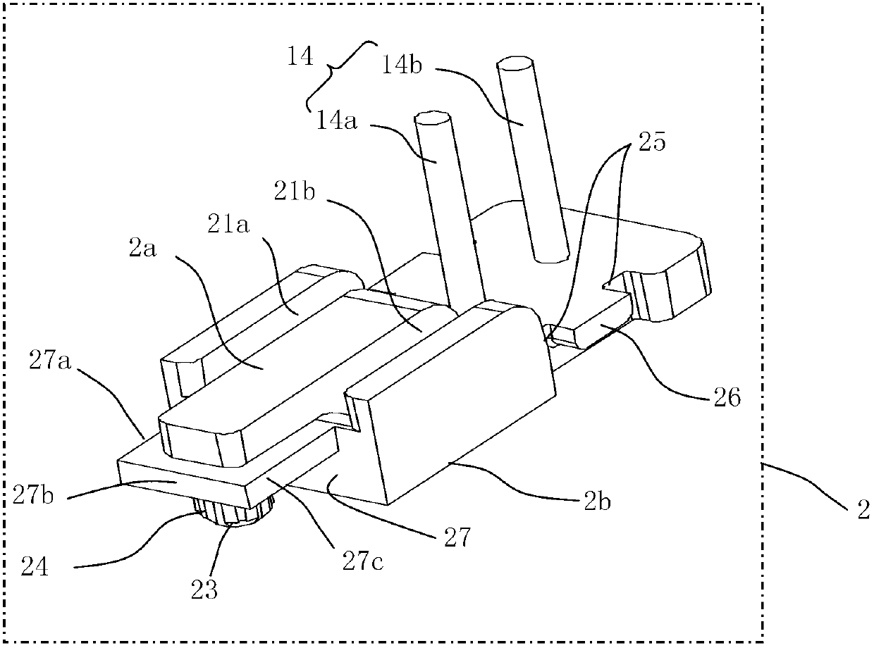
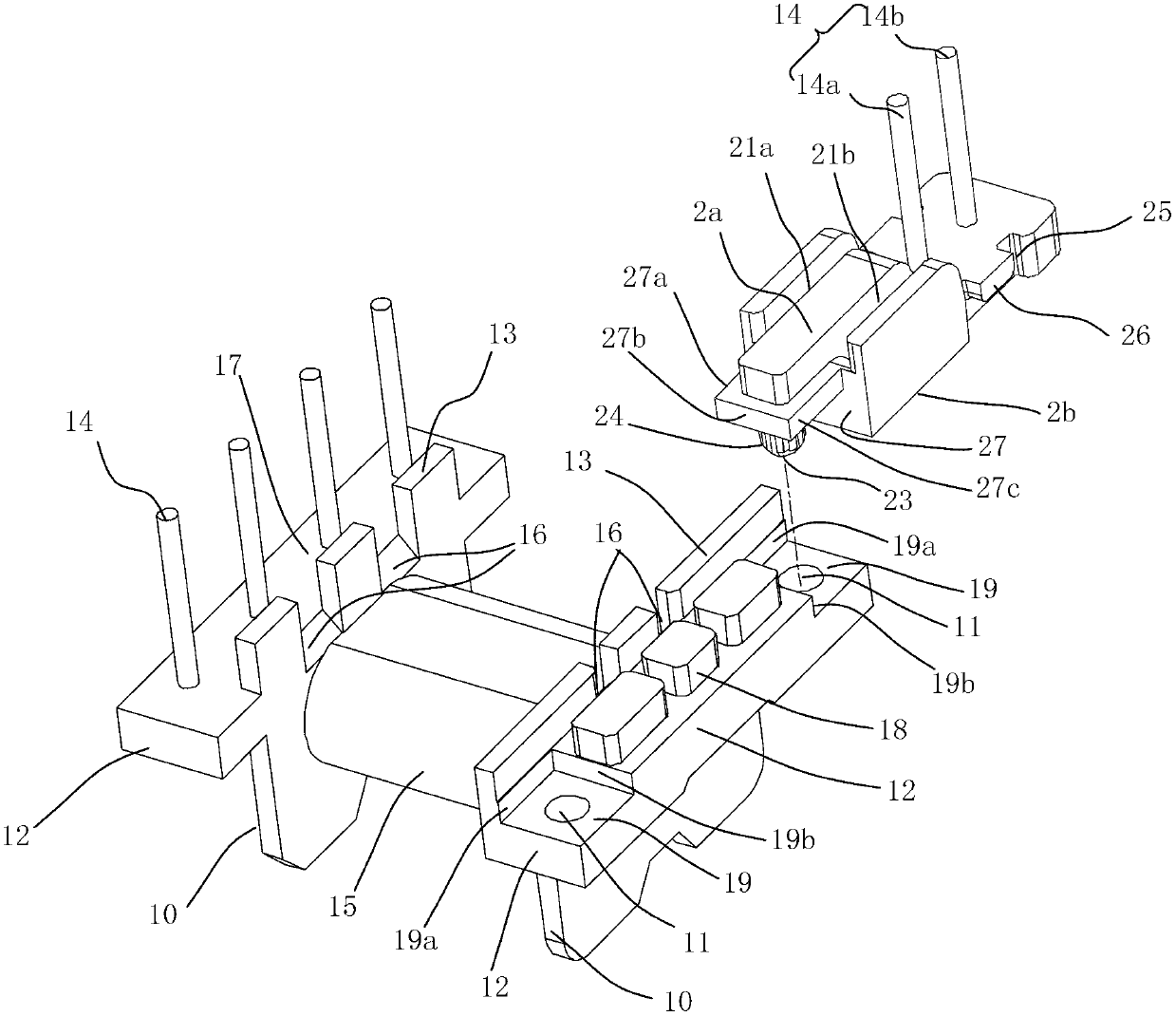
[0035] Such as Figure 1-7As shown, it is a combined adjustable transformer skeleton of the present invention, including a frame body, which is mainly composed of a main frame 1 and at least one connector 2. The main frame 1 includes a cylindrical winding part 15 and a horizontally arranged The wiring part and the socket at both ends of the winding part are the winding carrier of the transformer. The elongated horizontal support plate 12 supporting the magnetic core 4, the wiring part also includes at least one metal winding terminal 14 vertically arranged on the lower surface 17 of the support plate 12. In this embodiment, there are 4 winding terminals along the supporting plate. The longitudinal arrangement of the board 12; the plug connector 2 is mainly composed of an elongated horizontal mounting plate and a winding terminal 14 vertically arranged on the lower surface of one end of the mounting plate. There is at least one winding terminal. There are two wire terminals, w...


PUM


Abstract

The invention discloses a combined adjustable transformer bobbin. The transformer bobbin comprises a bobbin body which is mainly composed of a main frame and at least one plug connector. The main frame comprises a winding part, and a wiring part and a bayonet socket which are respectively transversally arranged at the two ends of the winding part; the wiring part and the bayonet socket both comprise a long horizontal support plate, and the wiring part further comprises at least one wiring terminal vertically arranged on the lower deck of the support plate; the plug connector mainly comprises a long horizontal mounting plate and at least one wiring terminal vertically arranged on the lower face of one end of the mounting plate; and a connecting structure is arranged the upper face of the other end of the mounting plate and the lower face of the support plate of the bayonet socket. The invention further discloses a transformer which applies the bobbin. Through the matching and assembling of the main frame and the plug connector and the adjustment of the mounting angle of the plug connector, the electric gap and the electric creepage distance are increased to satisfy the standard requirement and to realize isolation of the single circuit or a plurality of circuits of a primary winding and a secondary winding. According to the combined adjustable transformer bobbin, the volume of the transformer is reduced, saves arrangement room of the circuit board is reduced and the difficulty is reduced in the production process.

Description

technical field [0001] The invention relates to an electronic transformer, in particular to a combined adjustable transformer skeleton and a transformer using the skeleton. Background technique [0002] The transformer skeleton is the main structural component of the electronic transformer. Its main functions are: ⑴ Provide winding space for the copper wire in the transformer; ⑵ Carry the magnetic core; ⑶ The wire slot in the skeleton provides a path for the wire to pass when the transformer is wound; ⑷ The metal pins in the skeleton are the transformer copper wire Winding pillars; after soldering, they are connected to the PCB board, which plays the role of electrical connection when the transformer is working; (5) The baffle at the bottom of the skeleton can make the transformer and the PCB board produce a fixed position; it is the tin pile generated during soldering Provide spacing with PCB board, magnetic core and PCB board. [0003] In various safety standards such as...

Claims


Application Information

Patent Timeline
IPC IPC(8): H01F27/30H01F27/00H01F27/29
Inventor 向宇峰
Owner MORNSUN GUANGZHOU SCI & TECH
Learn More