Oscillating drip irrigation emitter
A sprinkler and water tank technology, applied in watering devices, climate change adaptation, gardening, etc., can solve the problems of high oscillation pulse frequency and difficult design and application of positive feedback oscillation pulse generators, etc., and achieve high-efficiency energy dissipation effect , increase anti-clogging ability, reduce the effect of flow index
- Summary
- Abstract
- Description
- Claims
- Application Information
AI Technical Summary
Problems solved by technology
Method used
Image
Examples
Embodiment 1
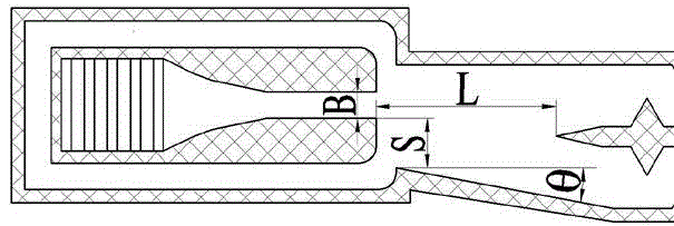
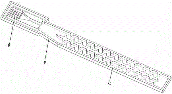
[0021] Embodiment 1: refer to figure 1 and image 3 The oscillating drip irrigation emitter shown in this embodiment is composed of a water inlet tank E, an oscillating element F and a flow channel body C. The water inlet trough E is provided with a filter window 1 and communicates with the inlet of the oscillating element F, and the outlet of the oscillating element F is connected to the flow channel body C. The inlet of channel body C is connected; the oscillating element F is composed of nozzle 3, control channel 4, control port I5, control port II6, jet space 7, inclined side wall 8, straight side wall 9, splitter splitter 10, straight jet outlet 11. Composed of oblique jet outlet 12; the jet space 7 of the oscillating element F is an asymmetric structure of a right-angled trapezoid, the right-angled side of the trapezoid is the straight side wall 9, and the hypotenuse is the inclined side wall 8; the front end of the oscillating element F is the nozzle 3. Control port Ⅰ5...
Embodiment 2
[0026] refer to Figure 4 , Image 6 , the basic structural features are similar to those of Embodiment 1, and the difference from Embodiment 1 is that the top of the splitter 10 is in a concave arc shape, and the two flow channels are arranged in a U-shape. 13 communicates with the straight jet outflow tank 17, and the oblique jet flow channel 14 communicates with the oblique jet outflow tank 16. The size of the oscillating element F varies, refer to Figure 5 , the nozzle width B is 0.8mm, the ratio of the headroom S on the straight jet side to the nozzle width B is 1:1.0, the ratio of the headroom S on the oblique jet side to the nozzle width B is 1:1.9, the split distance L and the nozzle width The ratio of B is 1:6.8, the opening angle θ is 10.5°, and the ratio of nozzle depth to nozzle width B is 1:1.2.
PUM
 Abstract
Description
Claims
Application Information
 - R&D
- Intellectual Property
- Life Sciences
- Materials
- Tech Scout
- Unparalleled Data Quality
- Higher Quality Content
- 60% Fewer Hallucinations
Browse by: Latest US Patents, China's latest patents, Technical Efficacy Thesaurus, Application Domain, Technology Topic, Popular Technical Reports.
© 2025 PatSnap. All rights reserved.Legal|Privacy policy|Modern Slavery Act Transparency Statement|Sitemap|About US| Contact US: help@patsnap.com


