Method for continuously and linearly adjusting output laser polarization direction of semiconductor nanowire

A polarization direction and nanowire technology, applied in the field of continuous linear adjustment, to achieve stable reliability, simple device structure, and easy operation

Inactive Publication Date: 2014-04-16
ZHEJIANG UNIV
View PDF2 Cites 0 Cited by
  • Summary
  • Abstract
  • Description
  • Claims
  • Application Information

AI Technical Summary

Problems solved by technology

However, there is no relevant report on the research on continuously linearly adjusting the polarization direction of the semiconductor nanowire output laser.

Method used


Image

  • Method for continuously and linearly adjusting output laser polarization direction of semiconductor nanowire
  • Method for continuously and linearly adjusting output laser polarization direction of semiconductor nanowire
  • Method for continuously and linearly adjusting output laser polarization direction of semiconductor nanowire

Examples


Embodiment 1

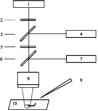
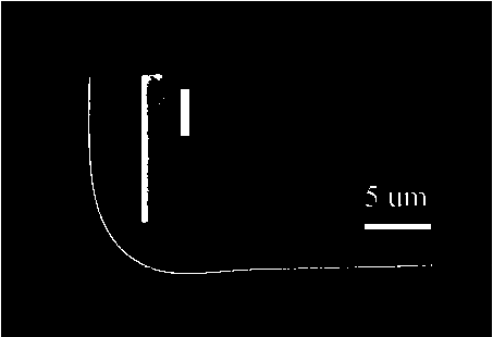
[0015] it will image 3 The shown CdSe nanowires with a diameter of 0.26um and a length of 40um are placed on a magnesium fluoride substrate 10, image 3 It is the scanning electron microscope picture of the CdSe nanowire. It can be seen from the illustration that the flatness of the end face is ideal. Under the microscope, the nanofiber probe 9 is used to bend one end of the CdSe nanowire to 1 degree with the horizontal line, and the pump pulse laser light emitted by the 532 nm pulse laser 7 enters the 50 times objective lens 8 through the beam splitter 6 and focuses on the other end of the CdSe nanowire for further processing. Pump excitation, the laser light generated by the excitation is emitted from the curved end of the CdSe nanowire, the laser light generated by the excited CdSe nanowire and the 532 nm pump pulse laser pass through the objective lens 8, and the 532 nm pump pulse laser light is filtered out by the 532 nm filter 5 After that, it passes through the beam s...

Embodiment 2

[0017] It puts ZnO nanowires with a flat end surface of 0.1um in diameter and 10um in length on a silica gel substrate 10, and bends one end of the ZnO nanowires to 100 degrees with the horizontal line through a nanofiber probe 9 under a microscope, and a 310nm pulse laser 7 The emitted pump pulse laser passes through the beam splitter 6 and enters the 100x objective lens 8 to focus on the other end of the ZnO nanowire for pumping excitation. The laser generated by the excitation exits from the bent end of the ZnO nanowire, and the laser generated by exciting the ZnO nanowire and 310 The nanometer pump pulse laser passes through the objective lens 8, passes through the 310 nanometer filter plate 5 to filter out the 310 nanometer pump pulse laser light, and then passes through the beam splitter 3, wherein, a part of it goes to the CCD 4 for imaging analysis, and the other part goes to the spectrometer 1 for spectrum analysis. Analysis, the polarizer 2 is placed in front of the s...

Embodiment 3

[0019] Place a CdS nanowire with a flat end surface of 2um in diameter and a length of 60um on a glass substrate 10, bend one end of the CdS nanowire to 45 degrees with the horizontal line through a nanofiber probe 9 under a microscope, and the 325nm pulse laser 7 emits The pump pulse laser enters the 80x objective lens 8 through the beam splitter 6 and focuses on the other end of the CdS nanowire for pumping excitation. The laser generated by the excitation exits from the bent end of the CdS nanowire, and the laser generated by the excited CdS nanowire and the 325 nm pump The pump pulse laser passes through the objective lens 8, and after the 325 nm pump pulse laser is filtered out by the 325 nm filter plate 5, then passes through the spectroscope 3, wherein, a part goes to the CCD 4 for imaging analysis, and another part goes to the spectrometer 1 for spectrum analysis. The polarizer 2 is placed in front of the spectrometer 1 to control the laser light with different polariza...


PUM


Abstract

The invention discloses a method for continuously and linearly adjusting the output laser polarization direction of a semiconductor nanowire. The method comprises the following steps: the semiconductor nanowire with a flat end surface is placed on a substrate; by the microscope, one end of the semiconductor nanowire is bent through a probe; pump pulse laser emitted by a pulse laser enters an objective lens by a spectroscope to be focused at the other end of the nanowire for excitation; laser and the pump pulse laser generated by excitation pass the objective lens, the pump pulse laser is filtrated by a filter sheet; part of the remaining laser enters a CCD (Charge Coupled Device), and the other enters a spectrometer through the spectroscope to obtain a linear relationship of a maximum polarization direction of laser emitted by the bending end of the nanowire and a bending angle of the nanowire, so that continuously and linearly adjusting for the output laser polarization direction can be realized by changing the bending angle of the nanowire. The invention is simple in structure and easy to operate and has stable output and high repeatability, and the output laser polarization direction of the bending end can be continuously and linearly adjusted by changing the bending angle of the nanowire.

Description

technical field [0001] The invention relates to a method for continuously linearly adjusting the polarization direction of semiconductor nanowire output laser. Background technique [0002] As the basic components of micro-nano optical devices and integrated circuits, semiconductor nanowires have aroused great interest of researchers in recent years. Since the semiconductor nanowire itself can not only be used as a gain medium, but its two end faces with good reflectivity can also make it a Fabry-Perot resonator cavity, the semiconductor nanowire is an excellent nanolaser with a high surface area. —The volume ratio also makes it easy to form various microstructures through micromanipulation. Typically, the guided wave modes supported in semiconductor nanowires have polarization directions perpendicular to the axis of the nanowire. However, there is no relevant report on the research on continuously linearly adjusting the polarization direction of the laser output from semi...

Claims


Application Information

Patent Timeline
Patent Type & Authority Patents(China)
IPC IPC(8): H01S5/30
Inventor 杨青杨伟松伍晓芹马耀光
Owner ZHEJIANG UNIV
Why Eureka
Try Eureka