Activated sludge-biofilm reactor and treatment method of organic wastewater

A biofilm reactor, activated sludge technology, applied in water/sludge/sewage treatment, chemical instruments and methods, water/sewage multi-stage treatment, etc., can solve the problems of long aeration cycle and high energy consumption, and achieve The effect of shortening the microbial denitrification process, saving energy, and increasing the content of easily biodegradable organic matter

Inactive Publication Date: 2013-01-23
CHINESE RES ACAD OF ENVIRONMENTAL SCI
View PDF4 Cites 9 Cited by
  • Summary
  • Abstract
  • Description
  • Claims
  • Application Information

AI Technical Summary

Problems solved by technology

If only aerobic treatment is used, the aeration period is long and the energy consumption is high, so it may not be able to achieve good treatment effect

Method used


Image

  • Activated sludge-biofilm reactor and treatment method of organic wastewater
  • Activated sludge-biofilm reactor and treatment method of organic wastewater

Examples


Embodiment 1

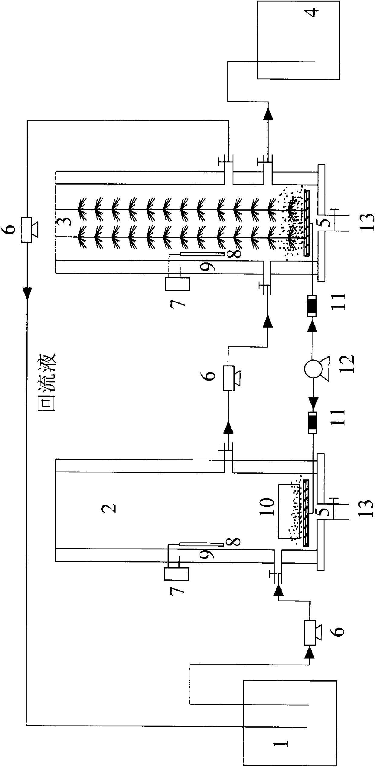
[0040] Please combine figure 1 , The wastewater and the reflux liquid are mixed in the distribution tank 1, and are introduced into the activated sludge reactor 2 under the action of the water pump 6, and the agitator 10 is turned on at the same time, so that the activated sludge and the wastewater are fully mixed, and the first stage anaerobic reaction is carried out. After the wastewater is filled with the activated sludge reactor 2, the water pump 6 is turned off. After 12 hours, the second stage anoxic reaction is started, the nano aerator 12 is turned on, and the aeration plate 5 is aerated under the control of the rotameter 11. After the second stage ends, the third stage of anaerobic reaction starts, which is the same as the first stage.

[0041] After the reaction in the activated sludge reactor is completed, the agitator 10 is turned off, the sludge and water are separated for a period of time after precipitation, and it flows into the aerobic biofilm reactor 3 for reacti...

Embodiment 2

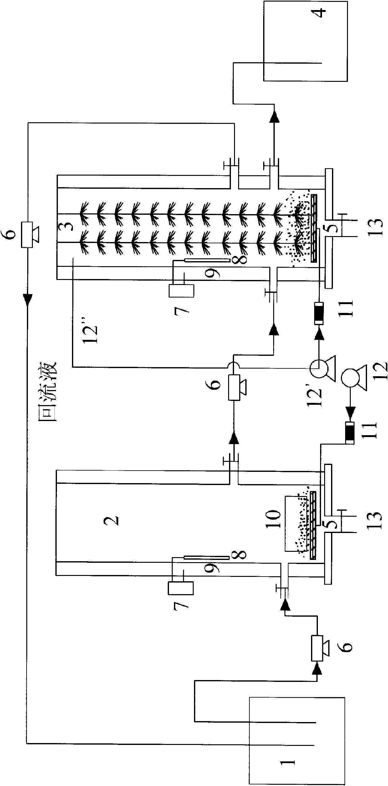
[0051] The activated sludge-biofilm reactor of this embodiment is basically the same as that of Embodiment 1. The difference is that the aerator of the aerobic biofilm reactor 3 of this embodiment is a nano-aerator 12', and is connected to the upper part of the aerobic biofilm reactor 3 through a water inlet pipe 12'.

[0052] The nano-aerator of this embodiment can generate a large number of micro-bubbles. When these nano-bubbles are dissolved in water, the water is milky white, which increases the specific surface area of ​​gas-liquid mass transfer, thereby improving the efficiency of gas-liquid mass transfer. Moreover, the slow rising speed of nanobubbles greatly increases the gas-liquid contact area and contact time, which is beneficial for the bubbles to dissolve in water and increase the concentration of dissolved oxygen in the water. To a certain extent, it overcomes the shortcomings of oxygen insoluble in water. This makes the use of nano-aeration has its own unique adva...


PUM


Abstract

The invention discloses an activated sludge-biofilm reactor for treating ammonium-nitrogen organic wastewater. The main structure is that a distribution reservoir is connected with a water inlet of an activated sludge reactor by a water pump, a sludge outlet is arranged at the bottom of the reactor, an aeration device is arranged above the sludge outlet inside the reactor, an agitator is arranged above the aeration device, a water outlet of the reactor is connected to the water inlet of an aerobic biofilm reactor by the water pump, a sludge outlet is arranged at the bottom of the aerobic biofilm reactor, an aeration device is arranged above the sludge outlet inside the aerobic biofilm reactor, an aerobic biofilm is grown on fillers inside the aerobic biofilm reactor, the aerobic biofilm reactor is respectively provided with two water outlets, wherein a first water outlet is connected to a discharge tank and a second water outlet is connected to the distribution reservoir, and an aerator is connected with the aeration devices of the activated sludge reactor and the aerobic biofilm reactor, respectively. The invention further discloses a method for treating ammonium-nitrogen organic wastewater.

Description

Technical field [0001] The invention belongs to sewage treatment technology, and specifically relates to an activated sludge-biofilm reactor for treating organic wastewater. [0002] The invention also relates to a method for treating high ammonia nitrogen organic wastewater by using the above-mentioned device. Background technique [0003] Ammonia nitrogen is an important cause of eutrophication in water bodies. At present, on the one hand, the discharge of ammonia nitrogen continues to increase, on the other hand, the national emission standards for ammonia nitrogen are more stringent. Therefore, it is necessary to study effective and fast ammonia nitrogen treatment technology. [0004] At this stage, the main treatment methods of ammonia nitrogen include physics, chemistry, biology and physicochemical methods. Among them, the biological treatment method is relatively traditional and is also a widely used method. At the same time, the biological method has relatively low cost and ...

Claims


Application Information

Patent Timeline
Patent Type & Authority Applications(China)
IPC IPC(8): C02F9/14
Inventor 席北斗王雷夏训峰张列宇王金生牛永超赵颖李晓光
Owner CHINESE RES ACAD OF ENVIRONMENTAL SCI
Why Eureka
Try Eureka