Coded aperture imaging system and coding code plate thereof

An imaging system and coded aperture technology, applied in the direction of using the diaphragm/collimator, etc., can solve the problems of limited integration and portability improvement, code plate processing, difficult fixing, code code plate pattern complex, etc., to achieve saving Heavy metal shielding material, improved portability, and improved resolution

Active Publication Date: 2013-01-23
北京高能新技术有限公司
View PDF4 Cites 18 Cited by
  • Summary
  • Abstract
  • Description
  • Claims
  • Application Information

AI Technical Summary

Problems solved by technology

[0012] 1. The encoding method is complicated, and the encoding code plate is composed of several "isolated" units, which have no support for each other, and it is difficult to process and fix the code plate
[0013] 2. Although the circular nesting method can be used to expand the field of view, at the same time, the caliber (area) of the probe equipped with collimator and detector in the entire coding control imaging system is expanded to four times that of the or

Method used


Image

  • Coded aperture imaging system and coding code plate thereof
  • Coded aperture imaging system and coding code plate thereof
  • Coded aperture imaging system and coding code plate thereof

Examples


Embodiment Construction

[0032] Typical embodiments embodying the features and advantages of the present invention will be described in detail in the following description. It should be understood that the present invention is capable of various changes in different embodiments without departing from the scope of the present invention, and that the description and drawings therein are illustrative in nature and not limiting. this invention.

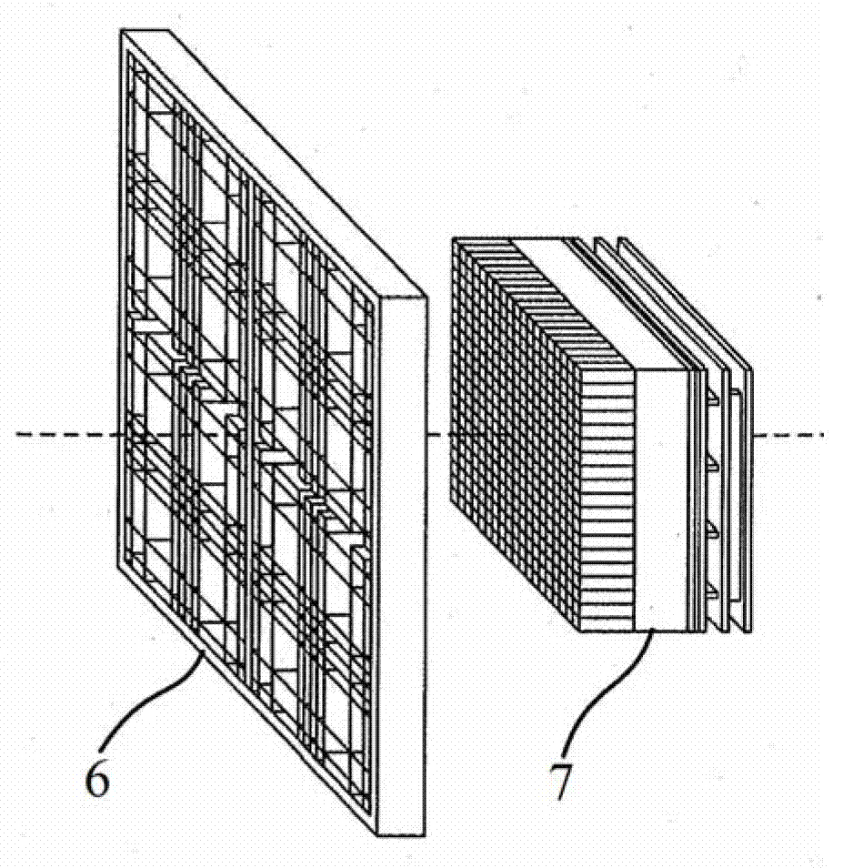
[0033] The encoding code plate of the embodiment of the present invention can be used in the encoding aperture imaging system of the embodiment of the present invention.

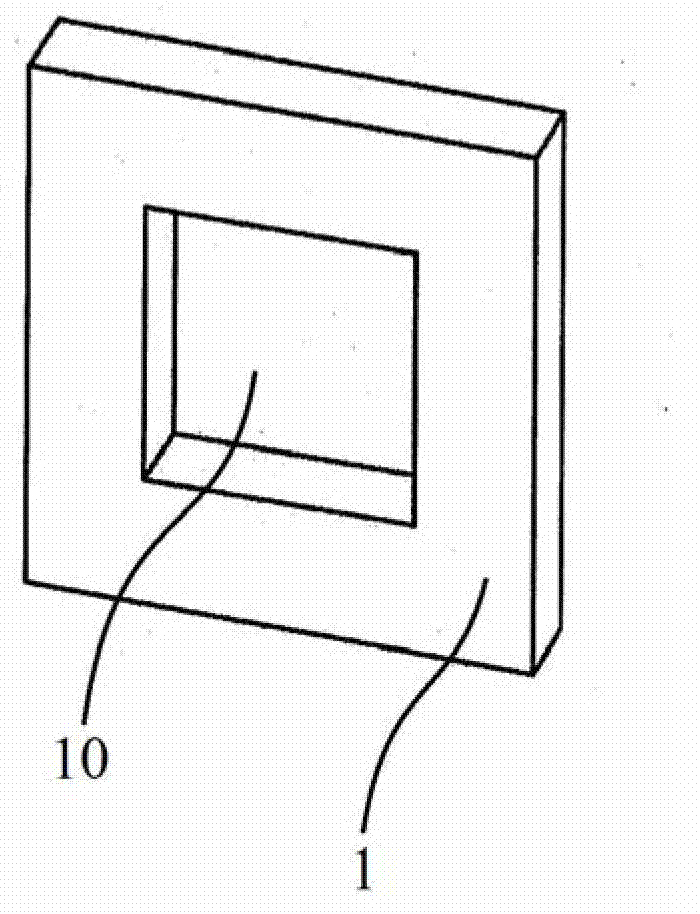
[0034] The present invention proposes a new type of square coding method, which is based on a coding code plate, including metal parts and one or more openings, within the range of any size (4N+1)×(4N+1), open The sum of the size of the hole is (2N+1)×(2N+1), and any two sizes within the range of (4N+1)×(4N+1), the patterns of the holes are not exactly the same, if The matrix of (4N+1)×(4N+1)...


PUM


Abstract

The invention discloses a coded aperture imaging system and a coding code plate thereof. The coding code plate comprises a metal part and one or more open holes; and in any range with the size of (4N+1) * (4N+1) of the coding code plate, the sum of the sizes of the open holes is (2N+1) * (2N+1), the any two sizes are in the range of (4N+1) * (4N+1), and the patterns of the open holes are not all the same. The coding code plate disclosed by the invention can not introduce the noise of the system due to the coding way; and furthermore, the coding code plate disclosed by the invention is simple in structure, reduces the processing difficulty and cost, and improves the assembly precision.

Description

technical field [0001] The invention relates to the technical field of radiation detection and imaging, in particular to an encoding code plate and an encoding aperture imaging system using the encoding code plate. Background technique [0002] At present, radioactive detection imaging technology has been widely used in nuclear industry, radioactive environmental monitoring, entry-exit security inspection and other fields to monitor the storage, transportation and use of radioactive materials. The core of this ray imaging technology is the design of collimator and detector. The radiation emitted by the radiation source passes through the collimator to produce a certain projection shape, and the detector interacts with the radiation to generate a measurement signal, thereby realizing the measurement of the projection image, and then reconstructing the image of the radiation source through an algorithm. [0003] In the traditional radiation detection imaging technology, imagi...

Claims


Application Information

Patent Timeline
IPC IPC(8): G21K1/02
Inventor 魏龙帅磊章志明李道武马创新刘彦韬王英杰张译文王晓明黄先超柴培唐浩辉李婷朱美玲庄凯姜小盼周魏孙世峰
Owner 北京高能新技术有限公司
Why Eureka
Try Eureka