

Thermopile infrared detector, array and preparation method of thermopile infrared detector
An infrared detector and thermopile technology, which is applied in electrical radiation detectors, piezoelectric devices/electrostrictive devices, piezoelectric/electrostrictive/magnetostrictive devices, etc., can solve problems such as process incompatibility, and achieve Solve the effect of incompatibility with IC process, reduce production cost and increase absorption area
Active Publication Date: 2013-01-30
中科芯未来微电子科技成都有限公司
View PDF3 Cites 27 Cited by
- Summary
- Abstract
- Description
- Claims
- Application Information
AI Technical Summary
Problems solved by technology
However, gold black coating and silver black coating are generally produced by resistance heating vacuum evaporation method, which is not compatible with IC (Integrated Circuit, integrated circuit) process
Method used
View moreImage
Smart ImageViewing Examples

Examples
preparation example Construction
Login to View More PUM
 Abstract
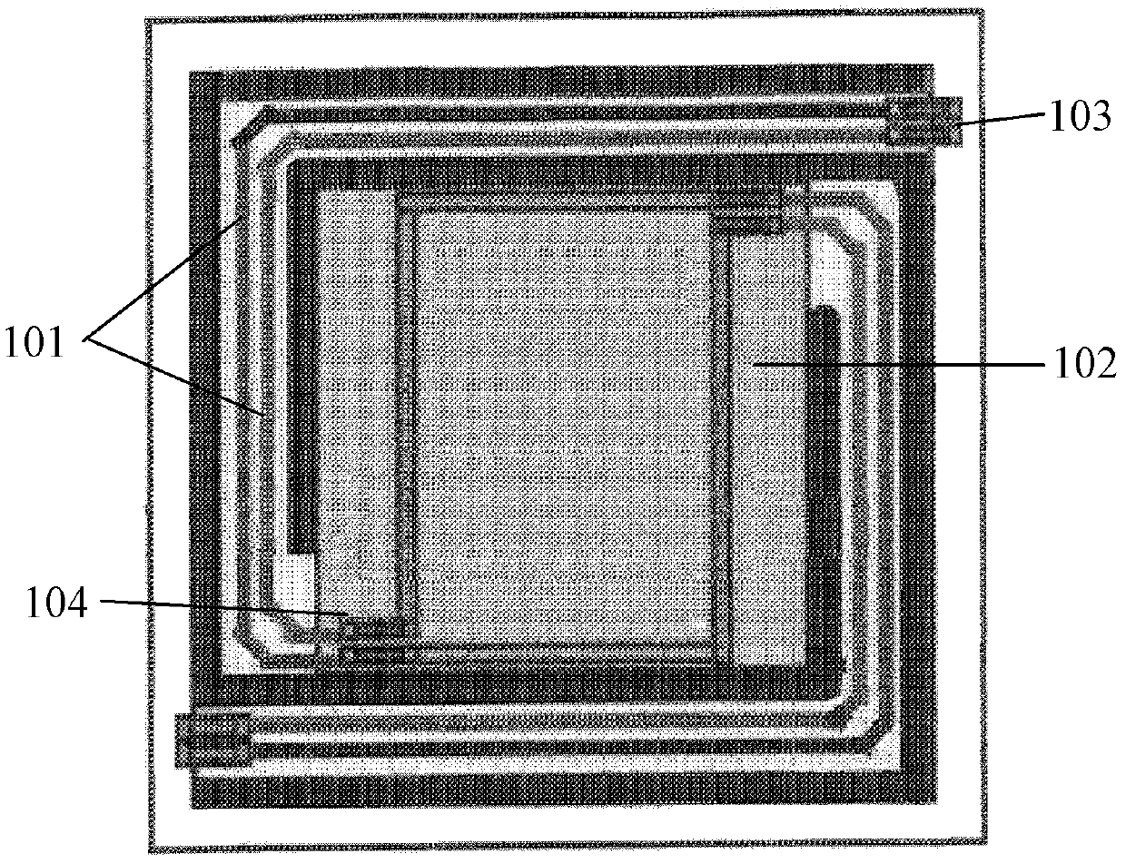
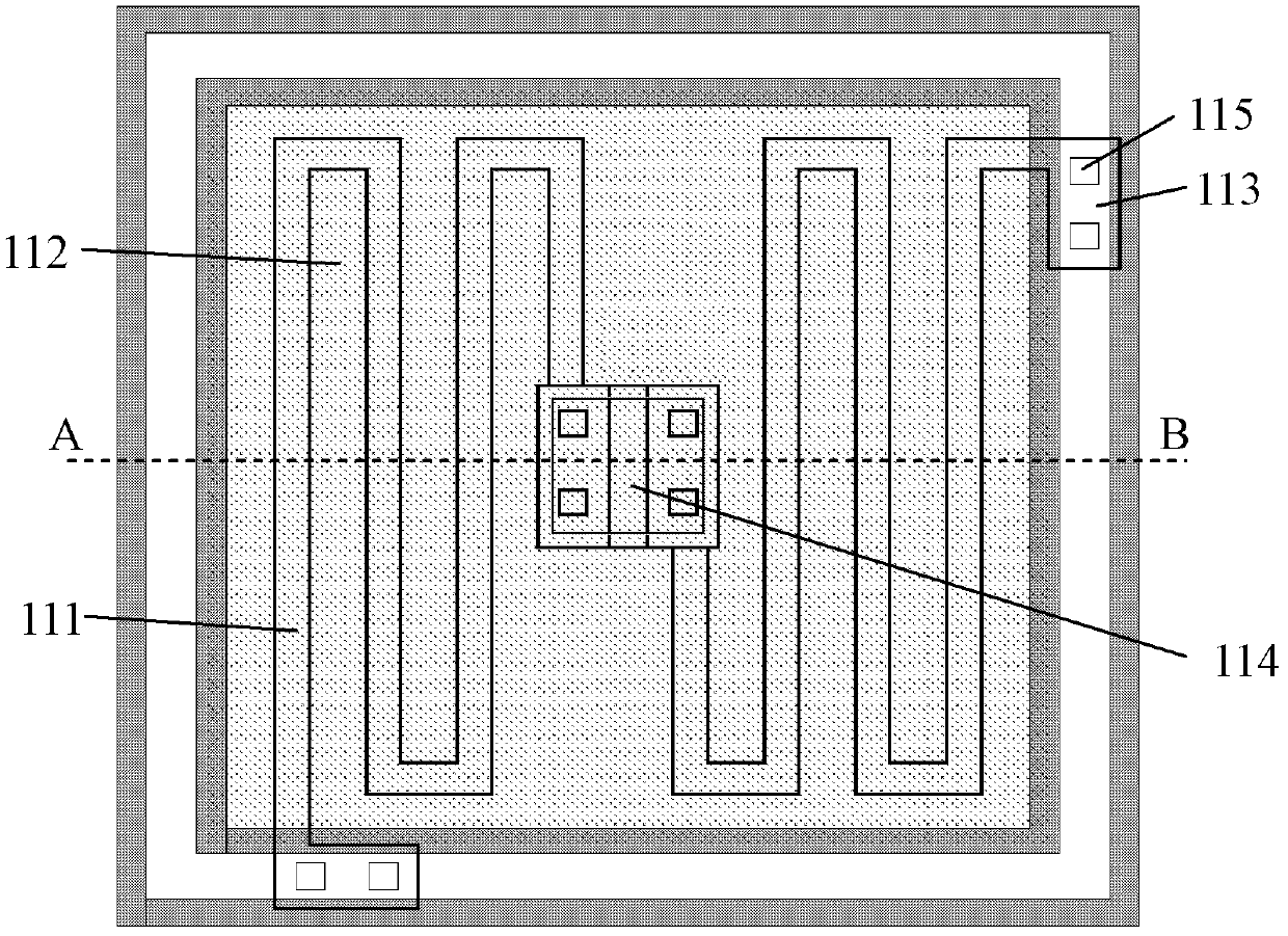
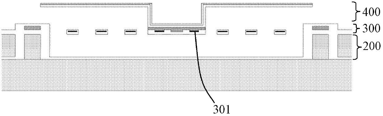
The invention provides a thermopile infrared detector and an array thereof. The thermopile infrared detector comprises a supporting part, a thermocouple part and an infrared absorption part. The supporting part comprises a supporting column and a cavity, the thermocouple part is suspended above the supporting part, a cold end of the thermocouple part is connected with the supporting column, and the infrared absorption part is positioned above the thermocouple part and connected with a hot end of the thermocouple part. Correspondingly, the invention further provides a preparation method of the thermopile infrared detector. The infrared absorption part and the thermocouple part of the thermopile infrared detector are not coplanar, the area of the infrared absorption part is unlimited by thermocouple number, and the infrared absorption part can maximally cover the whole thermocouple part, so that infrared absorption efficiency can be improved. An infrared absorption layer is made of black silicon materials, the preparation method is compatible to semiconductor IC (integrated circuit) process, and accordingly preparation cost of the detector can be lowered.
Description
technical field The invention relates to the field of infrared detectors, in particular to the field of thermopile infrared detectors. Background technique With the continuous development of infrared detection technology, infrared detectors have been used as core components in infrared temperature measurement, infrared detection, infrared alarm, infrared imaging, infrared guidance and other fields. The thermopile infrared detector is a kind of thermal detector, which mainly uses the thermoelectric effect to detect the change of the temperature of the object. A thermopile is composed of two or more thermocouples connected in series, and the thermoelectric potentials output by each thermocouple are superimposed on each other to form the thermoelectric potential of the thermopile. For common thermopile infrared detectors, an important parameter to characterize its characteristics is the responsivity, which is related to factors such as infrared absorption efficiency, detector ...
Claims
Login to View More Application Information
Patent Timeline
 IPC IPC(8): G01J5/12B81B3/00B81B7/04B81C1/00
CPCG01J5/12
Inventor赵利俊欧文
Owner中科芯未来微电子科技成都有限公司