Spectrum detection rod capable of continuously measuring

A technology for spectrum detection and light source measurement, which is applied in the field of spectrum detection rods, can solve the problems of unfavorable movement and detection anytime and anywhere, difficulty in continuous measurement and accurate detection, and no automatic online calibration, etc., to reduce the cycle of repeated calibration and the accuracy of data The effect of improving reliability and authenticity and improving detection accuracy

Inactive Publication Date: 2013-01-30
TIANHE AUTOMATION TECH SUZHOU +1
View PDF6 Cites 4 Cited by
  • Summary
  • Abstract
  • Description
  • Claims
  • Application Information

AI Technical Summary

Problems solved by technology

The existing technology has the following technical problems: (1) The existing measuring devices generally make the system into a desktop, and the detection medium is placed in a vessel with a fixed optical path, and then the vessel is placed in the middle of the optical path for detection, which requires sampling. It is not conducive to mobile and detection anytime and anywhere, and it is difficult to truly realize continuous measurement and actual accurate detection. (2) Although the existing measurement device has reference light detection, there is no means of automatic online calibration for the light intensity and wavelength of the light source and Method, (3) Since the light intensity of the measurement light source will attenuate due to the aging of the device after working for a period of time, there is inaccurate measurement, especially for concentration detection, which will bring a large deviation

Method used


Image

  • Spectrum detection rod capable of continuously measuring

Examples


Embodiment

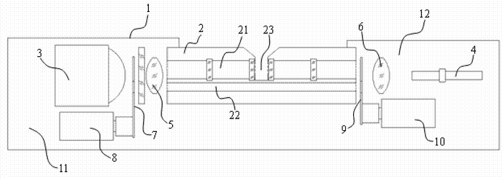
[0018] Embodiment: a kind of spectrum detection stick that can measure continuously, as attached figure 1 As shown, it includes a tube body 1, a glassware pool 2 located in the middle of the tube body 1, a measurement light source 3 and an MMS photosensor 4. The glassware pool 2 has a first optical path channel 21 for the measurement spectrum to pass through and a reference The second optical path channel 22 through which the spectrum passes. The glassware pool 2 has a groove 23 on the first optical path channel 21 that can hold the object to be tested. The front part of the tube body 1 is formed by the first rear cover and one end of the glassware pool 2 The first sealed cavity 11, the second sealed cavity 12 is formed by the second rear cover and the other end of the glassware pool at the rear of the tube body, the measuring light source 3 is located in the first sealed cavity 11, and the first convex lens 5 is located between the measuring light source 3 and the first sealed...


PUM


Abstract

The invention discloses a spectrum detection rod capable of continuously measuring, which comprises a tube body, a glassware pool, a measure light source and a MMS light inductor, the glassware pool has a first optical path channel capable of being passed by the measure spectrum and a second optical path channel capable of being passed by the reference spectrum, the glassware pool has a groove on the second optical path channel, the front part of the tube is a first seal chamber formed by a first rear cover and one end of the glassware pool, the rear part of the tube is a second seal chamber formed by a second rear cover and the other end of the glassware pool, the measure light source is positioned in a first seal chamber, a first convex lens is positioned between the measure light source and the glassware pool, the MMS light inductor is positioned in the second seal chamber, a second convex lens is positioned between the MMS light inductor and the glassware pool, a spectrum attenuator is positioned in the first seal chamber, and a light blocking sheet is positioned in the second seal chamber. The spectrum detection rod can be directly placed to a point to be measured of the environment to be measured, the real-time on-site environment is tested, and the measure precision can be enhanced due to added compensation effect of the spectrum attenuator.

Description

technical field [0001] The invention relates to the detection field, in particular to a spectrum detection stick capable of continuous measurement. Background technique [0002] In many fields such as chemical production, environmental monitoring, and emission monitoring, it is necessary to monitor and analyze the concentration components of gases and liquids. Spectrometry is an important method for continuous monitoring of gas concentration. In spectroscopic component concentration analysis, the analyte is in the sample cell, and the measurement light is incident from one end of the sample cell, and after passing through the gas to be measured, it is transmitted from the other end of the sample cell and enters the spectral analysis instrument or enters the optical fiber through the optical fiber. spectrometer. In this kind of measuring instrument, how to arrange the optical path, make the structure of the instrument as simple and reliable as possible, and reduce the size ...

Claims


Application Information

Patent Timeline
Patent Type & Authority Applications(China)
IPC IPC(8): G01N21/25G01N21/01
CPCG01N21/274
Inventor 钟旭东
Owner TIANHE AUTOMATION TECH SUZHOU
Why Eureka
Try Eureka