Small-diameter permanent-magnetic spherical polishing head with uniform distribution of magnetic field and design method for optimizing structural parameters of same
A technology of magnetic field distribution and structural parameters, applied in grinding/polishing equipment, surface polishing machine tools, calculations, etc., can solve the problem of magnetorheological fluid adsorption thickness and inconsistent strength, affecting workpiece shape accuracy and processing surface quality, polishing head Non-uniform magnetic field distribution and other problems, to achieve the effect of easy popularization and application, improved material removal rate, and simple structure
- Summary
- Abstract
- Description
- Claims
- Application Information
AI Technical Summary
Problems solved by technology
Method used
Image
Examples
specific Embodiment approach 1
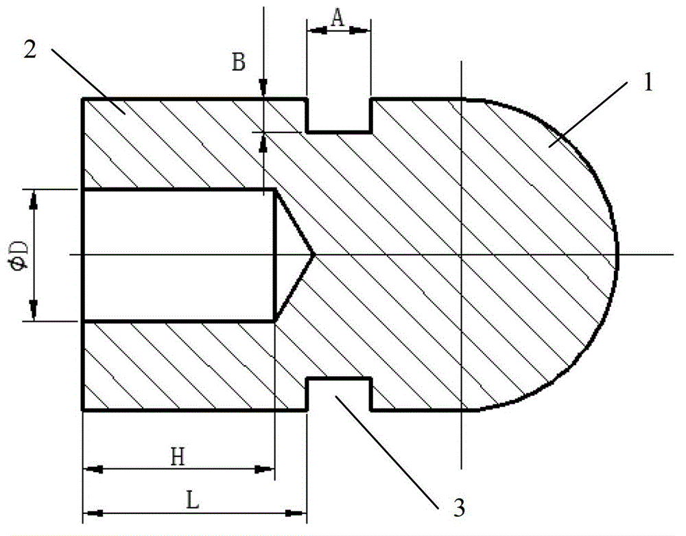
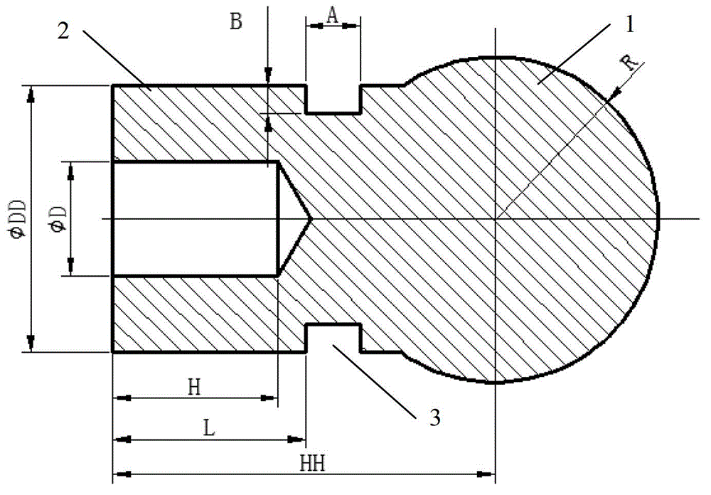
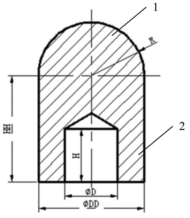
[0037] Specific embodiment one: the small-diameter permanent magnet spherical polishing head of the uniform magnetic field distribution described in this embodiment is a symmetrical structure, and described spherical polishing head is made up of ball head 1 and club 2, and described club 2 is that diameter is DD is a cylinder, the end center of the club 2 has an assembly hole with a diameter of D, and the depth of the assembly hole is H, and the head end of the club 2 is fixed with a ball head 1, and the ball head 1 has a radius R part of the sphere, and the center of the ball head 1 is located on the axis of the club 2, and the distance between the center of the ball head 1 and the end of the club 2 is HH. An annular groove 3 is arranged on the outer surface of the shaft, the width of the annular groove 3 is A, the depth is B, and the distance between the annular groove 3 and the end of the club 2 is L.
[0038] The permanent magnet polishing head described in this embodiment...
specific Embodiment approach 2
[0039] Embodiment 2: This embodiment is a further limitation of the small-diameter permanent magnet spherical polishing head with uniform magnetic field distribution described in Embodiment 1. In this embodiment, the radius R of the ball head 1 is equal to the club 2 half of the diameter DD.
[0040] The permanent magnet spherical polishing head described in this embodiment is based on the existing polishing head structure, and an annular groove is added. This kind of structure is more convenient to manufacture, and it is easy to achieve higher precision, and the magnetic field is evenly distributed. It is suitable for magnetic field Preparation of polishing heads with low strength requirements and small processing surfaces, suitable for most polishing head manufacturing situations.
specific Embodiment approach 3
[0041]Embodiment 3: This embodiment is a further limitation of the small-diameter permanent magnet spherical polishing head with uniform magnetic field distribution described in Embodiment 2. In this embodiment, the annular groove 3 is along the length direction of the club 2 The width A of the groove 3 is greater than 1.5 mm and less than or equal to 2 mm, the depth B of the groove 3 is greater than 0 mm and less than or equal to 0.3 mm, and the distance L between the annular groove 3 and the end of the club 2 is greater than 1.5 mm and less than or equal to 1.8 mm. mm, the diameter D of the assembly hole is greater than 2.0mm and less than or equal to 2.5mm, the depth H of the assembly hole is greater than 2.5mm and less than or equal to 4mm, and the radius of the ball head 1 is 1.8mm.
[0042] This embodiment is a further limitation on the structural parameters of the permanent magnet spherical polishing head described in the second embodiment. Next, the simulation method i...
PUM
| Property | Measurement | Unit |
|---|---|---|
| Width | aaaaa | aaaaa |
| Depth | aaaaa | aaaaa |
| Diameter | aaaaa | aaaaa |
Abstract
Description
Claims
Application Information
 - R&D
- Intellectual Property
- Life Sciences
- Materials
- Tech Scout
- Unparalleled Data Quality
- Higher Quality Content
- 60% Fewer Hallucinations
Browse by: Latest US Patents, China's latest patents, Technical Efficacy Thesaurus, Application Domain, Technology Topic, Popular Technical Reports.
© 2025 PatSnap. All rights reserved.Legal|Privacy policy|Modern Slavery Act Transparency Statement|Sitemap|About US| Contact US: help@patsnap.com


