Distributed exposure dose control system and method

A technology of exposure dose and control system, applied in the field of integrated circuit equipment manufacturing, which can solve the problems of inaccurate compensation, time lag, and dependence on accuracy, etc.

Active Publication Date: 2013-02-06
SHANGHAI MICRO ELECTRONICS EQUIP (GRP) CO LTD
View PDF10 Cites 13 Cited by
  • Summary
  • Abstract
  • Description
  • Claims
  • Application Information

AI Technical Summary

Problems solved by technology

However, the current exposure method simply performs closed-loop compensation based on the last measured pulse condition.
This compensation method relies too much on the accuracy of the sensor, and the compensation is not accurate enough simply from the measurement results. For example, the purpose is to compensate 3mJ, and the actual effect of the final adjustment may only be 2.8mJ. In addition, this compensation method still has Disadvantages of time lag

Method used


Image

  • Distributed exposure dose control system and method
  • Distributed exposure dose control system and method
  • Distributed exposure dose control system and method

Examples


Embodiment Construction

[0068] Specific embodiments of the present invention will be described in detail below in conjunction with the accompanying drawings.

[0069] The present invention is an implementation system of an exposure dose control system and related methods. The following describes the detailed implementation cases of related structures and steps of the present invention.

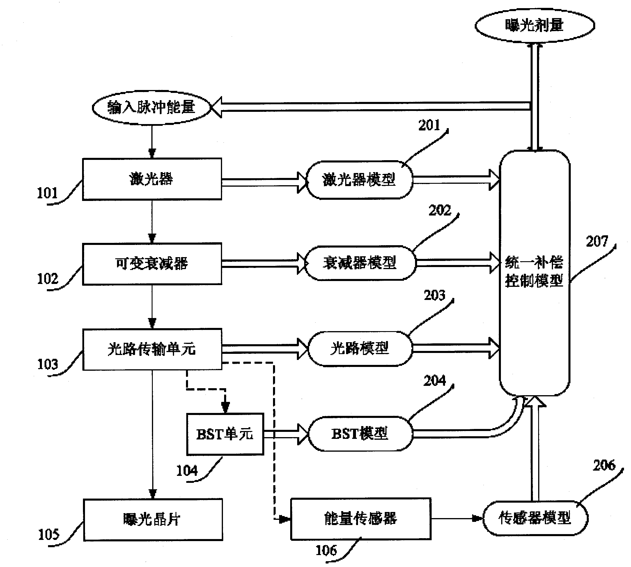
[0070] The method is based on an exposure dose control system, so first a brief description of the exposure dose control system is given. Such as figure 1 As shown, the input pulse energy value is first sent to the laser 101, and then the laser triggers the laser pulse. After the laser pulse is sent out, it will pass through the variable attenuator VA (102 and the optical path transmission unit 103, and reach the wafer 105 to realize exposure. The real value will be measured by the energy sensor 106 in the optical path and reflected to the system. Based on the aforementioned exposure process, when the system receive...


PUM


Abstract

The invention discloses a distributed exposure dose control system, which comprises a laser unit, a variable attenuator, a light path transmission unit, a light path guide unit and an energy sensor, wherein the laser unit generates a laser pulse, and then the energy sensor measures actually received laser pulse after the laser pulse passes through the variable attenuator, the light path transmission unit and the light path guide unit. The distributed exposure dose control system is characterized in that the laser unit, the variable attenuator, the light path transmission unit, the light path guide unit, and the energy sensor respectively adopt independent correction modules to obtain compensation factors of different units, obtain a pulse energy value after carrying out feed-forward compensation on the actually received laser pulse and related parameter according to calibrating factors of the different units, and carry out feedback compensation to obtain the optimal exposure dose after the pulse energy value is output by a uniform compensation control unit.

Description

technical field [0001] The invention relates to the field of integrated circuit equipment manufacturing, in particular to a distributed exposure dose control system and method for photolithography equipment. Background technique [0002] Dose control is an important part in photolithography. The exposure dose refers to the light energy of a specific wavelength absorbed by the photoresist per unit area of ​​the silicon wafer during the exposure process, that is, the integral of the exposure light intensity at a certain point on the silicon wafer surface to the exposure time: Where D is the exposure dose; T is the exposure time; I is the exposure light intensity, which is a function of time t. The exposure dose directly affects the final performance indicators of the lithography machine, including critical dimensions, uniformity of critical dimensions, final wafer quality and production efficiency, etc. Therefore, in order to improve the performance of the lithography machi...

Claims


Application Information

Patent Timeline
IPC IPC(8): G03F7/20
Inventor 孙智超罗闻张曦
Owner SHANGHAI MICRO ELECTRONICS EQUIP (GRP) CO LTD
Why Eureka
Try Eureka