Edge deletion method for thin-film solar cells
A technology of solar cells and thin-film solar energy, applied in circuits, electrical components, laser welding equipment, etc., can solve problems such as waste, and achieve the effects of reduced use costs, high edge cleaning efficiency, and improved laser energy utilization.
- Summary
- Abstract
- Description
- Claims
- Application Information
AI Technical Summary
Problems solved by technology
Method used
Image
Examples
Embodiment 1
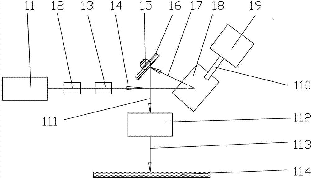
[0027] figure 1 It is a schematic diagram of the device structure of the galvanometer flat-field scanning ultrashort pulse laser edge-clearing device of the present invention, by figure 1 It can be known that the galvanometer flat-field scanning ultrashort pulse laser edge clearing of the present invention is specifically as follows: the ultrashort pulse width laser 11 emits laser light, and the laser beam passes through the laser beam expander 12 of 5 magnifications and the laser flat top element 13 to obtain the incident laser light 14, The incident laser light 14 obtains the first light beam 17 through the first reflection mirror 18 of the oscillating mirror, and the first light beam 17 obtains the second light beam 111 through the second reflection mirror 16 of the galvanometer, and the second light beam 111 passes through the far The central focusing mirror 112 obtains a focused beam 113 which directly acts on the material 114 to be processed.
[0028] The material 114 t...
Embodiment 2
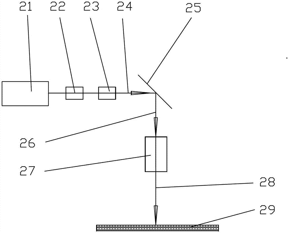
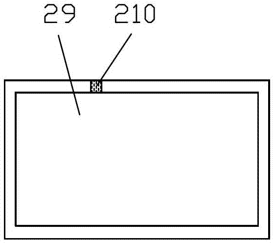
[0035] figure 2 It is a schematic diagram of the device structure of the rectangular static focus spot ultrashort pulse laser edge clearing device of the present invention, image 3 It is the plan view of the ultra-short laser edge-clearing of rectangular static focus spot of the present invention, by figure 2 as well as image 3 It can be seen that the flow process of the rectangular static focus spot ultra-short laser edge cleaning of the present invention is as follows: the ultra-short pulse width laser 21 emits laser light, and the laser beam passes through the laser beam expander 22 of 5 magnifications and the laser flat-top element 23 to obtain the first beam 24, The first light beam 24 passes through the reflector 25 to obtain the second light beam 26, and the second light beam 26 is focused by the static imaging focusing mirror 27 to obtain the focused light beam 28, and the focused light beam 28 directly acts on the material 29 to be processed, and the focused ligh...
PUM
| Property | Measurement | Unit |
|---|---|---|
| thickness | aaaaa | aaaaa |
| thickness | aaaaa | aaaaa |
Abstract
Description
Claims
Application Information
 - R&D
- Intellectual Property
- Life Sciences
- Materials
- Tech Scout
- Unparalleled Data Quality
- Higher Quality Content
- 60% Fewer Hallucinations
Browse by: Latest US Patents, China's latest patents, Technical Efficacy Thesaurus, Application Domain, Technology Topic, Popular Technical Reports.
© 2025 PatSnap. All rights reserved.Legal|Privacy policy|Modern Slavery Act Transparency Statement|Sitemap|About US| Contact US: help@patsnap.com


