Edge deletion method for thin-film solar cells

A technology of solar cells and thin-film solar energy, which is applied to circuits, electrical components, laser welding equipment, etc., can solve problems such as waste, and achieve the effects of reduced use cost, improved edge cleaning speed and laser energy utilization rate, and fast edge cleaning speed

Active Publication Date: 2013-02-06
张立国
View PDF5 Cites 41 Cited by
  • Summary
  • Abstract
  • Description
  • Claims
  • Application Information

AI Technical Summary

Problems solved by technology

[0005] We can think that during the laser edge cleaning process, the solar film is directly vaporized under the action of the laser. The total thickness of these films does not exceed 5 microns, and the total thickness of the solar film of most batteries does not even exceed 2 microns. The energy required can be determined according to the relevant The heat of vaporization of the material is calculated, but it is certain that most of the energy is not absorbed and wasted directly when a high-power infrared laser of 200W to 500W is used for laser edge cleaning.
This is because the conductive film of thin-film solar cells is transparent to visible light and has a certain transmittance to infrared light. Obviously, using infrared laser for laser edge cleaning is not a reasonable laser edge cleaning solution.

Method used


Image

  • Edge deletion method for thin-film solar cells
  • Edge deletion method for thin-film solar cells
  • Edge deletion method for thin-film solar cells

Examples


Embodiment 1

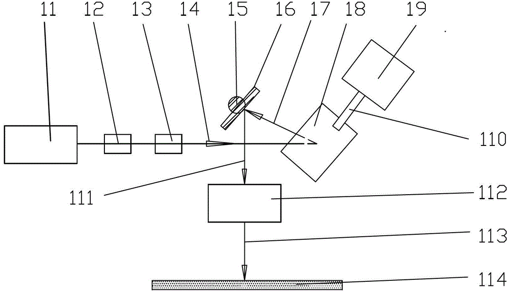
[0027] figure 1 It is a schematic diagram of the device structure of the galvanometer flat-field scanning ultrashort pulse laser edge-clearing device of the present invention, by figure 1 It can be known that the galvanometer flat-field scanning ultrashort pulse laser edge clearing of the present invention is specifically as follows: the ultrashort pulse width laser 11 emits laser light, and the laser beam passes through the laser beam expander 12 of 5 magnifications and the laser flat top element 13 to obtain the incident laser light 14, The incident laser light 14 obtains the first light beam 17 through the first reflection mirror 18 of the oscillating mirror, and the first light beam 17 obtains the second light beam 111 through the second reflection mirror 16 of the galvanometer, and the second light beam 111 passes through the far The central focusing mirror 112 obtains a focused beam 113 which directly acts on the material 114 to be processed.

[0028] The material 114 t...

Embodiment 2

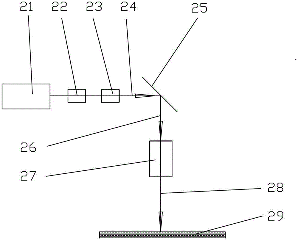
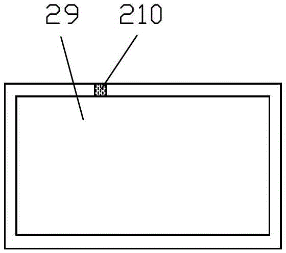
[0035] figure 2 It is a schematic diagram of the device structure of the rectangular static focus spot ultrashort pulse laser edge clearing device of the present invention, image 3 It is the plan view of the ultra-short laser edge-clearing of rectangular static focus spot of the present invention, by figure 2 as well as image 3 It can be seen that the flow process of the rectangular static focus spot ultra-short laser edge cleaning of the present invention is as follows: the ultra-short pulse width laser 21 emits laser light, and the laser beam passes through the laser beam expander 22 of 5 magnifications and the laser flat-top element 23 to obtain the first beam 24, The first light beam 24 passes through the mirror 25 to obtain the second light beam 26, and the second light beam 26 is focused by the static imaging focusing mirror 27 to obtain the focused light beam 28, and the focused light beam 28 directly acts on the material 29 to be processed, and the focused light b...


PUM

PropertyMeasurementUnit
thicknessaaaaaaaaaa
thicknessaaaaaaaaaa

Abstract

The invention belongs to the field of laser processing, discloses an edge deletion method for thin-film solar cells, and concretely relates to a method for carrying out edge deletion on thin-film solar cells by using ultra-short pulse laser. The method disclosed by the invention is importantly characterized in that high-peak-power ultra-short pulse laser with an extremely high transparent conductive film absorption rate is introduced into an application of carrying out edge deletion on thin-film solar cells. Compared with laser power used by edge deletion implemented by using infrared nanosecond laser, the method can complete high-efficiency and high-quality laser edge deletion by using smaller average laser power; and glass is not easy to be damaged, the compatibility with different kinds of transparent conductive films is extremely strong, and the application cost is reduced.

Description

technical field [0001] The invention belongs to the field of laser processing, in particular to the field of edge cleaning of laser thin film solar cells. Background technique [0002] At present, the development of thin-film solar energy is in the ascendant. The last process of thin-film solar glass substrate battery is to hermetically encapsulate the glass substrate. Thin film and active layer film) need to be cleaned, which is called edge cleaning or edge sweeping in the industry. The method of sandblasting was the first method, which was low in cost, but caused serious environmental pollution, so it was gradually eliminated. [0003] Using a laser to directly vaporize the surrounding area of ​​the battery glass through the glass is a relatively popular method at present. In order to meet the production rhythm of one piece of glass per minute, the industry usually uses a high-power infrared laser of 200W to 500W for laser edge cleaning. Since this kind of laser is a side...

Claims


Application Information

Patent Timeline
Patent Type & Authority Applications(China)
IPC IPC(8): H01L31/18B23K26/06B23K26/073B23K26/0622
CPCY02P70/50
Inventor 张立国
Owner 张立国
Why Eureka
Try Eureka