
Speed adjustable electromagnetic fan clutch structure with independent controller

An electromagnetic fan and clutch technology, applied in the direction of magnetic drive clutch, clutch, non-mechanical drive clutch, etc., can solve the problems of engine water temperature fluctuation, engine power waste, excessive heat dissipation capacity, etc., to reduce power loss, meet mass production, Easy to place effects

Inactive Publication Date: 2013-02-13
CHINA FIRST AUTOMOBILE
View PDF5 Cites 9 Cited by
  • Summary
  • Abstract
  • Description
  • Claims
  • Application Information

AI Technical Summary

Problems solved by technology

The current cooling system design standard is to solve the heat dissipation problem at full load, so excessive heat dissipation capacity at partial load will lead to waste of engine power
[0003] At present, the engine generally adopts the electromagnetic clutch cooling fan with relay switch control to replace the traditional silicon oil clutch cooling fan, which improves the temperature control accuracy and achieves the purpose of saving fuel; the commonly used electromagnetic fan clutch is mainly composed of a bimetallic temperature control switch and an electromagnetic The clutch is composed of series connection, the control circuit and the execution circuit are connected in series. When the bimetal temperature control switch passes a large current, the working point will drift, which will affect the control accuracy and cause the engine water temperature to fluctuate in a wide range.
At the same time, only closed-loop control is performed on the water temperature signal. Due to the thermal inertia of the engine system, even after the temperature controller starts to operate, the engine water temperature will continue to overshoot, resulting in low control accuracy of the system.

Method used


Image

  • Speed adjustable electromagnetic fan clutch structure with independent controller
  • Speed adjustable electromagnetic fan clutch structure with independent controller
  • Speed adjustable electromagnetic fan clutch structure with independent controller

Examples


Embodiment Construction

[0013] Further description will be made below in conjunction with the accompanying drawings and the reduction of diesel engine power loss described in the present invention.

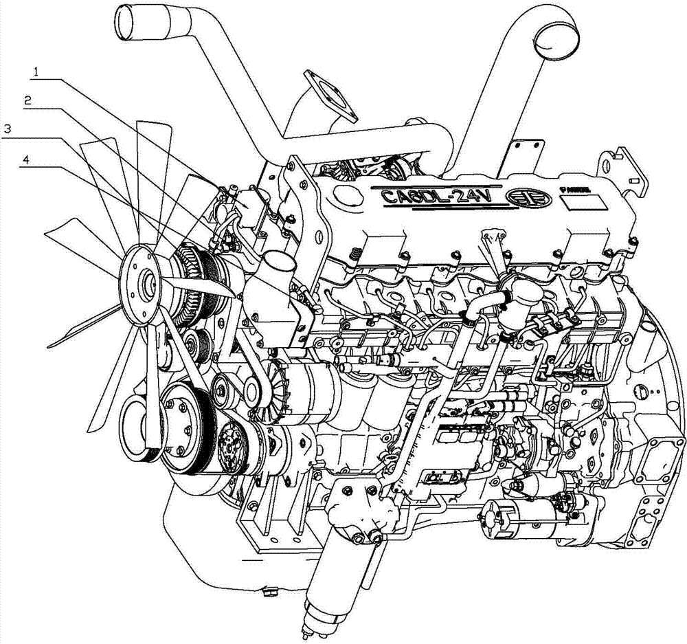
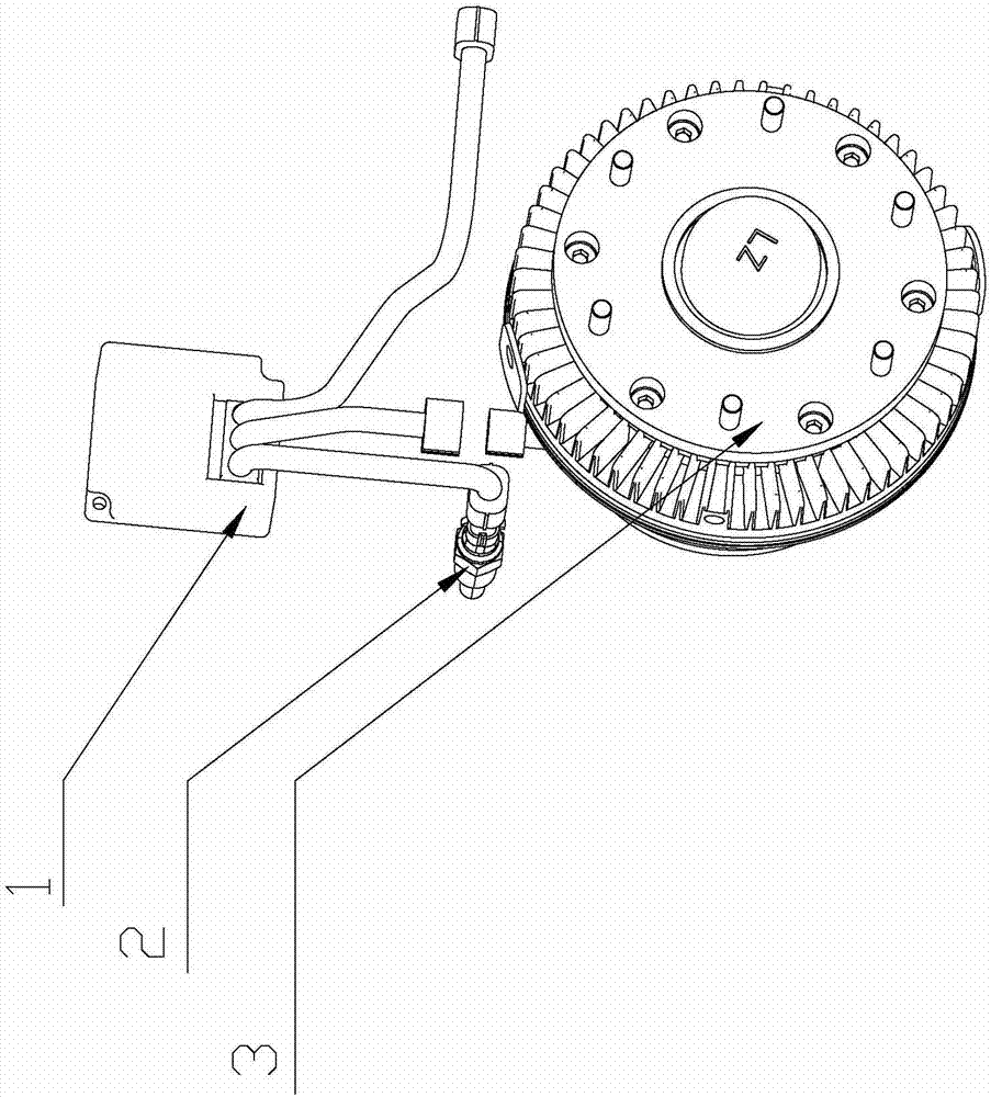
[0014] Such as Figure 1 ~ Figure 2 As shown, it includes a controller 1 with a microprocessor, a water temperature sensor 2, an electromagnetic fan clutch 3, and a vehicle connector 4.

[0015] The output end of the controller 1 with a microprocessor is connected to an electromagnetic fan clutch 3 , the temperature sensor 2 is connected to the controller 1 with a microprocessor, and the electromagnetic fan clutch 3 is connected to a vehicle connector 4 . The control loop is separated from the execution loop, the large current of the actuator will not affect the control loop, and the water temperature of the engine can be controlled at the optimum temperature.

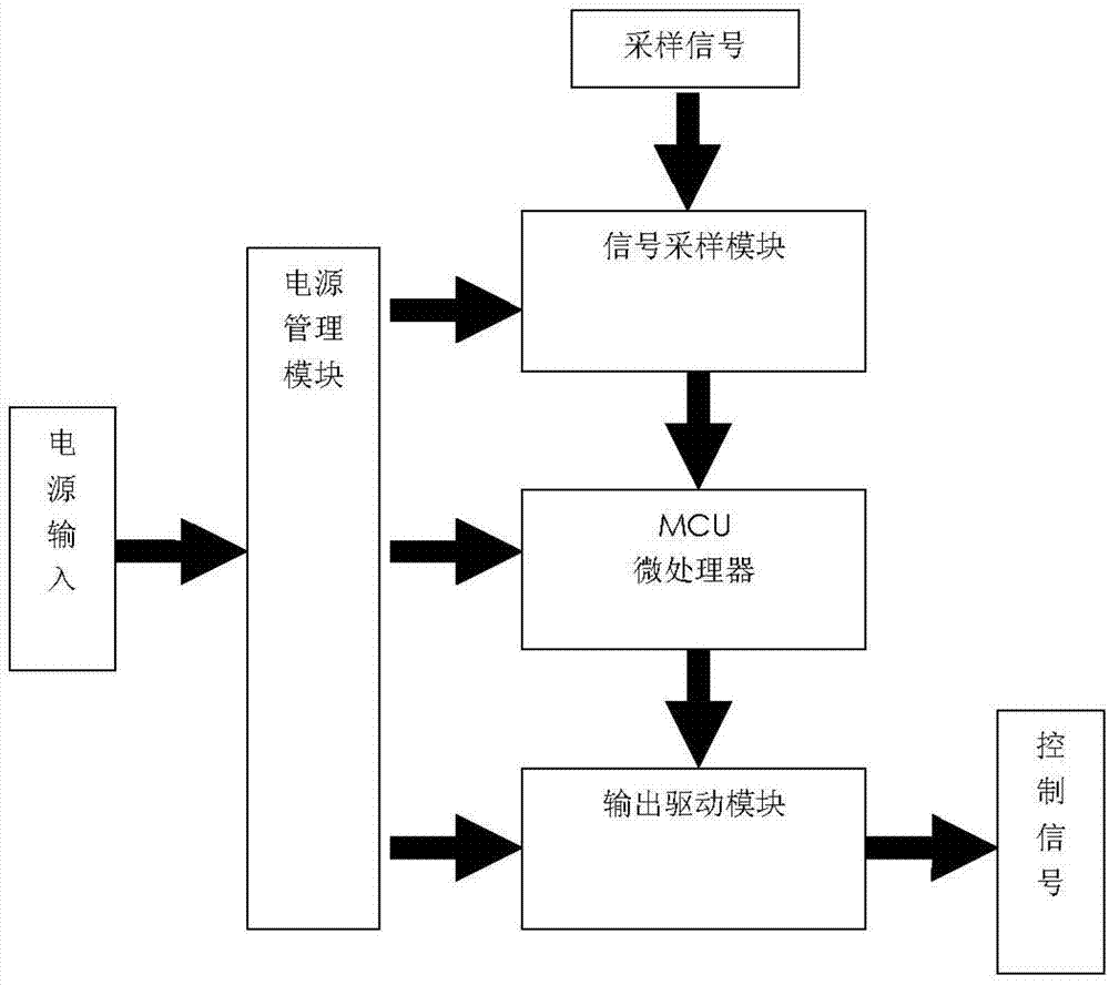
[0016] Such as image 3 As shown, the controller with a microprocessor includes a power management module, a signal sampling module, an MCU mi...


PUM


Abstract

The invention relates to an electromagnetic fan clutch structure for a diesel engine, in particular to a speed adjustable electromagnetic fan clutch structure with an independent controller. The speed adjustable electromagnetic fan clutch structure with the independent controller is used for adjusting the rotating speed of a radiating fan of the diesel engine. The invention belongs to the technical field of an engine. The speed adjustable electromagnetic fan clutch structure with the independent controller comprises an electromagnetic fan clutch and is characterized by further comprising a controller and a water temperature sensor, the controller is provided with a microprocessor, and an output end of the controller with the microprocessor is connected with the water temperature sensor, and the water temperature sensor is connected with the electromagnetic fan clutch. Signals such as water temperature, oil temperature of a torque converter and air-conditioning working state can be adopted so as to forecast various factors due to overflow water temperature, produce a control function in advance, and accordingly ensure stability of water temperature of a whole car. Meanwhile, the speed adjustable electromagnetic fan clutch structure with the independent controller is capable of reducing power loss of the diesel engine, reducing oil consumption of the whole car, and enabling the water temperature of the engine of the whole car to be always in a reasonable interval. The speed adjustable electromagnetic fan clutch structure with the independent controller is economic, practical, high-efficiency, and capable of meeting the requirement for mass production.

Description

technical field [0001] The invention relates to a structure of an electromagnetic fan clutch for a diesel engine, in particular to an adjustable-speed electromagnetic fan clutch with an independent controller for speed regulation of a cooling fan of a diesel engine, and belongs to the technical field of engines. Background technique [0002] Traditional engine cooling systems are passive, simple in structure or low in cost. The current cooling system design standard is to solve the heat dissipation problem at full load, so excessive heat dissipation capacity at partial load will result in waste of engine power. [0003] At present, the engine generally adopts the electromagnetic clutch cooling fan with relay switch control to replace the traditional silicon oil clutch cooling fan, which improves the temperature control accuracy and achieves the purpose of saving fuel; the commonly used electromagnetic fan clutch is mainly composed of a bimetallic temperature control switch a...

Claims


Application Information

Patent Timeline
Patent Type & Authority Applications(China)
IPC IPC(8): F01P7/12F01P7/04F16D27/14
Inventor 胡维嘉江伟董佳李政季建
Owner CHINA FIRST AUTOMOBILE
Learn More