Pupil shaping device for photoetching illumination

A shaping device and photolithography technology, which is applied in the direction of microlithography exposure equipment, photolithography exposure device, optics, etc., can solve the problems that the optical system is difficult to correct, cannot be overcome, and the manufacturing cost of the lithography machine is high, so as to achieve the overall transparency The effect of improving the efficiency, saving the processing cost and reducing the manufacturing cost

Active Publication Date: 2013-02-13
BEIJING GUOWANG OPTICAL TECH CO LTD
View PDF6 Cites 4 Cited by
  • Summary
  • Abstract
  • Description
  • Claims
  • Application Information

AI Technical Summary

Problems solved by technology

The main disadvantages of using this method are: the introduction of the conical lens group will cause the optical system to produce off-axis aberrations that are difficult to correct, which will deteriorate the light intensity distribution on the pupil surface, change the size of the tangential extreme angle of the pupil surface, and The radial light intensity distribution will also be affected; the introduction of the conical mirror group reduces the transmittance of the entire optical system, and the energy of the laser light source cannot be effectively used; the processing of the conical mirror working in the deep ultraviolet band is difficult, resulting in light The manufacturing cost of engraving machine is high
The pupil shaping device can increase the adjustment freedom of several illumination modes, but does not change the overall layout of the traditional shaping device, so it cannot overcome the above shortcomings

Method used


Image

  • Pupil shaping device for photoetching illumination
  • Pupil shaping device for photoetching illumination
  • Pupil shaping device for photoetching illumination

Examples


Embodiment Construction

[0031] The present invention will be further described below in conjunction with the accompanying drawings and embodiments, but the protection scope of the present invention should not be limited thereto.

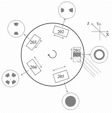
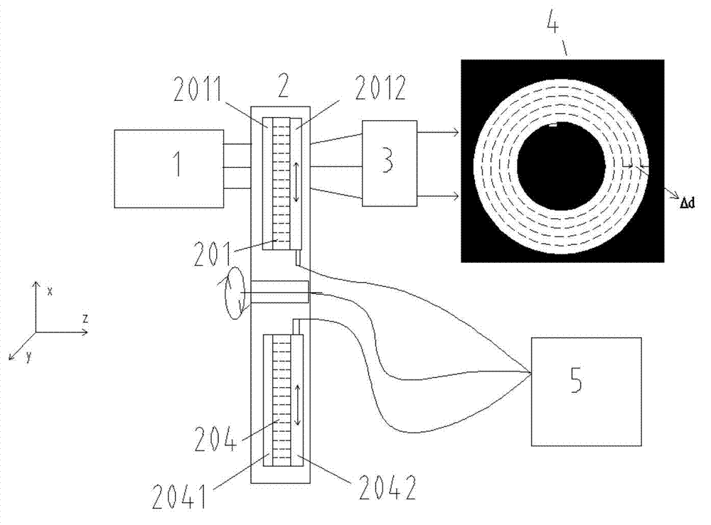
[0032] see first figure 1 , figure 1 It is a system structure diagram of the pupil shaping device for lithography illumination of the present invention, consisting of figure 1 It can be seen that the pupil shaping device for lithography illumination of the present invention includes a turntable mechanism 2 , a continuous zoom lens group 3 and a controller 5 .

[0033] where 1 is the size-invariant square incident beam generated in the illumination system of the lithography machine.

[0034] The turntable mechanism 2 contains a plurality of diffractive optical elements 201-205, please refer to image 3 , image 3 It is a schematic diagram of the turntable structure 2 of the present invention. The turntable mechanism 2 is evenly provided with five diffractive optical ele...


PUM


Abstract

The invention relates to a pupil shaping device for photoetching illumination. The pupil shaping device for the photoetching illumination is characterized in by comprising a rotating disc mechanism, a continuous zoom lens group and a controller, wherein the rotating disc mechanism is circumferentially uniformly provided with a plurality of diffractive optical elements; the diffractive optical elements of the rotating disc mechanism and the continuous zoom lens group are sequentially arranged along the direction of square incident light beams generated by a photoetching machine illuminating system; the diffractive optical elements are positioned on the front focal plane of the continuous zoom lens group and are perpendicular to the optical axis of the pupil shaping device; the controller accurately controls the rotation of the rotating disc mechanism and the movement of the diffractive optical elements through an encoder; and the focal distance of the continuous zoom lens group is regulated, and needed illuminating pupil distribution is formed on the image space focal plane, namely a pupil plane, of the continuous zoom lens group. The pupil shaping device disclosed by the invention has the advantages of simple optical system and high optical transmission rate, and can be used for solving the problem of pupil degradation, which is caused by a tapered lens group, of the existing pupil shaping device.

Description

technical field [0001] The invention relates to lighting equipment for a lithography machine, in particular to a pupil shaping device for adjusting the spatial distribution size of light intensity on a pupil surface in an off-axis lighting system of an ultraviolet lithography machine. Background technique [0002] In the illumination system of an advanced lithography machine, by selecting the spatial distribution size of the illumination light intensity on the pupil plane corresponding to the structure and size of the lithography mask pattern, especially by changing the inner diameter of the annular illumination zone on the pupil plane And the ring width, to improve the resolution of the lithography system, improve the contrast of lithography, so as to realize the precise processing of ultra-fine lithography patterns. The generation and adjustment of the spatial distribution of the illumination light intensity on the pupil plane is the function of the pupil shaping device. ...

Claims


Application Information

Patent Timeline
Patent Type & Authority Applications(China)
IPC IPC(8): G03F7/20G02B27/09
Inventor 陈明朱菁杨宝喜曾爱军黄惠杰胡中华李璟
Owner BEIJING GUOWANG OPTICAL TECH CO LTD
Why Eureka
Try Eureka