Field effect tube driving circuit

A technology for driving circuits and field effect transistors, applied in electrical components, adjusting electrical variables, instruments, etc., can solve problems such as difficulty in optimizing switching timing

Active Publication Date: 2013-02-13
江苏应能微电子有限公司
View PDF3 Cites 2 Cited by
  • Summary
  • Abstract
  • Description
  • Claims
  • Application Information

AI Technical Summary

Problems solved by technology

However, because there are thousands of FETs, and the turn-off speed of each type is different, it is difficult to optimize the

Method used


Image

  • Field effect tube driving circuit
  • Field effect tube driving circuit
  • Field effect tube driving circuit

Examples


Embodiment Construction

[0034] The invention is a field effect tube driving circuit, which can optimize the switching timing, thereby optimizing the function of the overshoot voltage. Please refer to Figure 9-10 , Figure 9 It is a block diagram of a field effect transistor drive circuit in a preferred embodiment of the present invention, Figure 10 It is a circuit diagram of a field effect transistor driving circuit in a preferred embodiment of the present invention. In this embodiment, a flyback circuit is taken as an example for illustration. The field effect transistor driving circuit 91 is used for driving the field effect transistor of the switching power supply 92 . The switching power supply 92 includes a switch 921 and a transformer circuit 922 connected thereto. The switch 921 is used to provide an AC signal to the transformer circuit 922 . The switch 921 is generally a field effect transistor, Figure 10 The component indicated by the symbol M4 in the figure is the main switching pow...


PUM


Abstract

The invention provides an efficient field effect tube driving circuit which is used for driving a switch power field effect tube. The field effect tube driving circuit comprises a work power supply, a driving signal generating circuit, a delay driving circuit and a delay circuit, wherein the driving signal generating circuit, the delay driving circuit and the delay circuit are connected with one another in sequence and further connected to the switch power field effect tube; the driving circuit comprises a slow disconnecting circuit and a rapid disconnecting circuit; the delay driving circuit comprises a first phase inverter, a second phase inverter and a voltage comparator; the first phase inverter provides driving signals to the slow disconnecting circuit, and the second phase inverter provides driving circuit signals to the rapid disconnecting circuit; the voltage comparator is positioned in front of the second phase inverter, and when driving signals of the inverted input end of the voltage comparator rises to be higher than one reference voltage, the rapid disconnecting switch is disconnected, and only is the slow disconnecting circuit connected; and until the first phase inverter and the second phase inverter are connected, the slow disconnecting circuit is disconnected.

Description

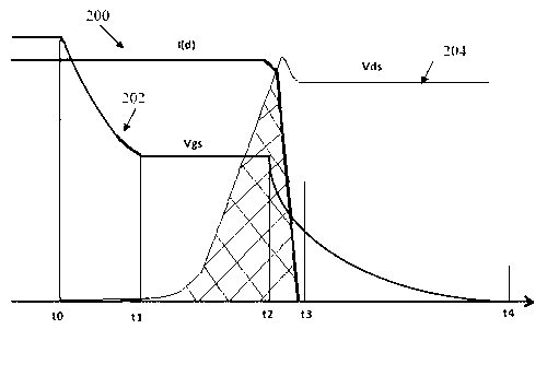
technical field [0001] The invention relates to a switching power supply technology, and in particular to a high-efficiency field effect transistor drive circuit, which is applied to a switching power supply. Background technique [0002] In many circuits, especially switching power supplies, field effect transistors are often used as switching elements to turn on and off a certain part of the circuit, especially the power conversion part of high current and high voltage. Because it is a high-power circuit, the field effect transistor often has to withstand a large current when it is turned on, and it often has to withstand a high voltage when it is blocked. Power loss occurs when the FET is blocked and turned on. [0003] figure 1 It is the waveform diagram when the FET is turned off. 200 is the current from the drain to the source of the FET. 204 is the drain to source voltage. 202 is the gate driving voltage. Taking the N-type field effect transistor as an example f...

Claims


Application Information

Patent Timeline
IPC IPC(8): H02M1/08H02M3/335
Inventor 朱伟东林峰
Owner 江苏应能微电子有限公司
Why Eureka
Try Eureka