Isothermal thermoforming hydraulic press

A warm forming and hydraulic press technology, applied in the field of hydraulic machinery, can solve the problems of increased forging difficulty, waste of energy, large heat loss, etc., and achieve the effects of improving the overall rigidity, compacting the overall structure, and reducing the span

Active Publication Date: 2016-08-31
TIANJIN TIANDUAN PRESS CO LTD
View PDF9 Cites 0 Cited by
  • Summary
  • Abstract
  • Description
  • Claims
  • Application Information

AI Technical Summary

Problems solved by technology

However, traditional forging machines generally use manual replacement of molds. When the mold needs to be replaced, the operator must wait until the temperature of the hydraulic press drops to normal temperature before operating.
After the mold is replaced and the workpiece is put in, the hydraulic press needs to be reheated and then pressed. Due to the frequent replacement of the mold and the traditional manual clamping method, the heat loss of the press is serious.
The working area of ​​traditional hydraulic equipment adopts an open structure, which leads to serious heat loss during the forging process, making it difficult for the forging temperature to reach an isothermal state; and the mold needs to be continuously heated to forge the next workpiece
This not only wastes a lot of energy, affects work efficiency, and increases production costs; it also makes forging more difficult and the yield is very low
In addition, the operating temperature of the hydraulic press in the known technology is generally within the temperature range of about 400°C, and its slider is guided by the four columns of the fuselage, which not only increases the span of the upper beam, but also increases the working furnace chamber of the hydraulic press. Surrounding, it is impossible to install insulation devices around the working furnace cavity, and the heat loss is large; and the material of the four columns is difficult to ensure that the slider can be accurately guided at a high temperature of about 900 ° C, so the traditional forging machinery can no longer meet the rapid development of the aviation industry. current situation

Method used


Image

  • Isothermal thermoforming hydraulic press
  • Isothermal thermoforming hydraulic press
  • Isothermal thermoforming hydraulic press

Examples


Embodiment Construction

[0021] In order to further understand the invention content, characteristics and effects of the present invention, the following examples are given, and detailed descriptions are as follows in conjunction with the accompanying drawings:

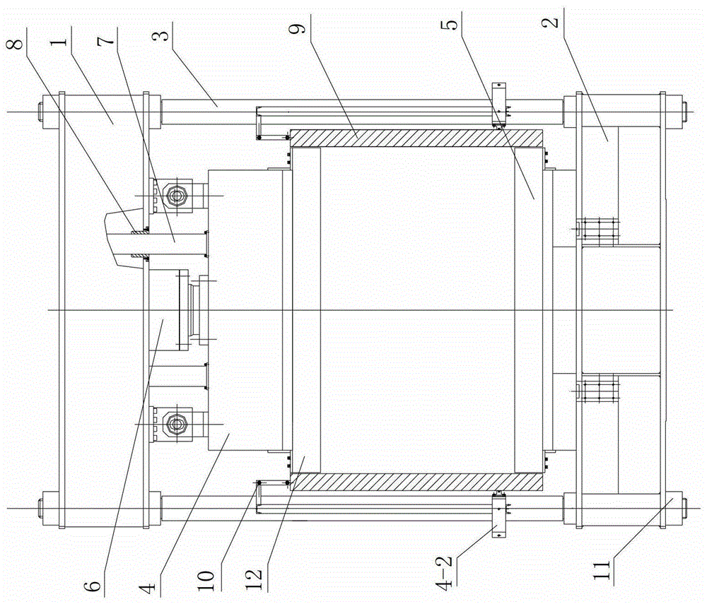
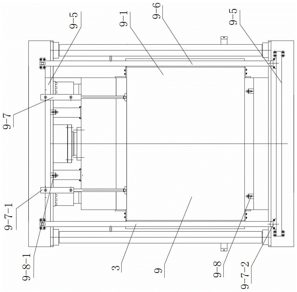
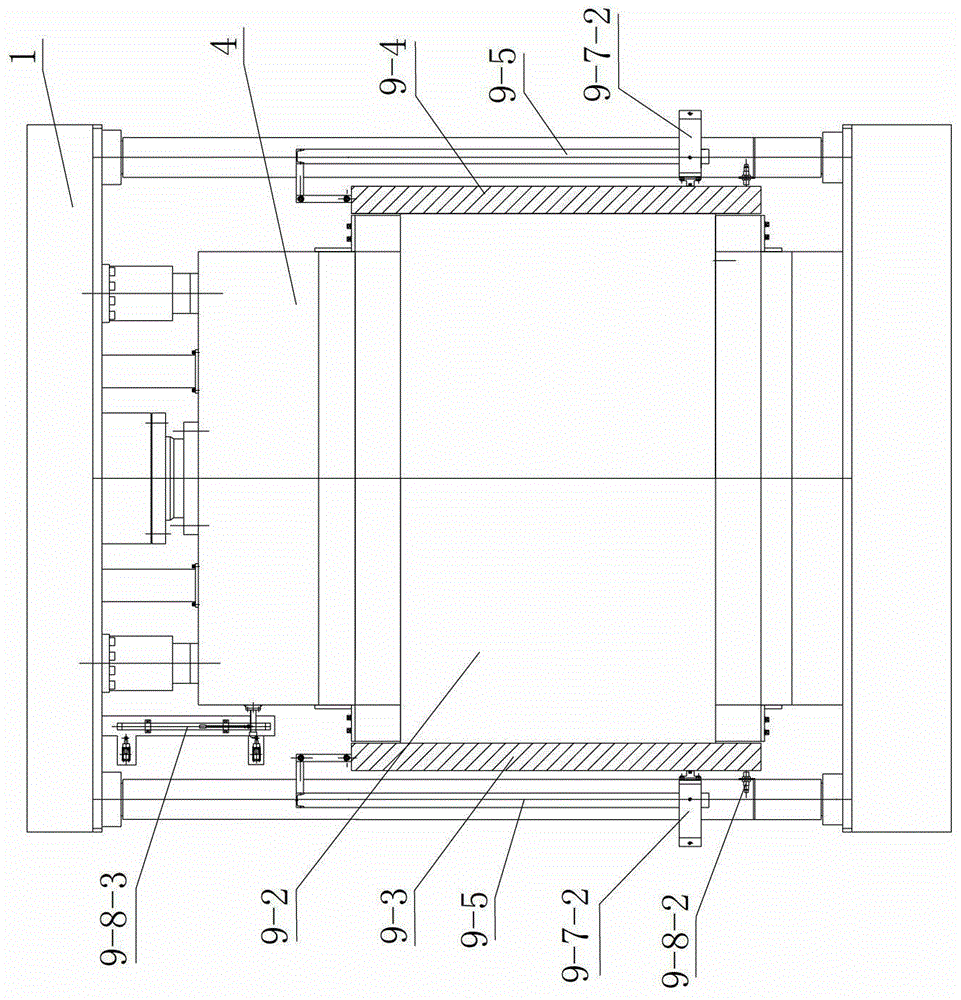
[0022] see Figure 1-Figure 4 , isothermal thermoforming hydraulic press, including three-beam four-column fuselage composed of upper beam 1, lower beam 2 and column 3 fastened by lock nut 11, working oil cylinder 6 installed on the upper beam, and slider connected with the working oil cylinder 4 and the workbench arranged on the lower beam. A guide column 7 for guiding the slider is mounted on the upper beam, and a guide sleeve 8 is provided between the upper beam and the guide column. In this embodiment, the guide sleeve between the upper beam and the guide column is Wear-resistant guide bush made of composite material. A heat-resistant ceramic plate 12 is fixedly mounted on the periphery of the lower plane of the slider. The workbench i...


PUM


Abstract

The invention relates to an isothermal thermal forming forging machine which comprises a three-beam and four-column machine body, a working oil cylinder, a sliding block and a worktable, wherein the three-beam and four-column machine body is formed by an upper beam, a lower beam and columns. The isothermal thermal forming forging machine is characterized in that a guide column used for guiding the sliding block is arranged on the upper beam in penetrating mode, a guide sleeve is arranged between the upper beam and the guide column, and a heat resistance ceramic plate is fixedly arranged on the periphery of the lower plane of the sliding block. A high temperature resistance metal base plate and a ceramic base plate are sequentially fixedly arranged on the moving worktable through fastening parts, a ceramic coaming is fixed on the periphery of the ceramic base plate through a coaming bracket, and a heat preservation device is arranged on the periphery of a working area of the forging machine. The isothermal thermal forming forging machine has the advantages that temperature in the working area can be sufficiently kept in the high temperature forging process, and workpiece thermal state pressing can be achieved; temperature loss is reduced to be minimum, energy sources can be saved greatly, production cost is reduced, and product forging quality is improved; and further processing requirements of the aerospace industry for airplane titanium alloy thermal forming parts and other isothermal thermal forming parts are met.

Description

technical field [0001] The invention belongs to the technical field of hydraulic machinery, in particular to an isothermal thermoforming hydraulic press. Background technique [0002] At present, in the forging process of isothermal hot forming of aircraft titanium alloy components, the forging temperature requirements are relatively strict, that is, the forging temperature should be kept within a temperature range of about 900 °C. However, traditional forging machines generally use manual replacement of molds. When the mold needs to be replaced, the operator must wait until the temperature of the hydraulic press drops to normal temperature before operating. After the mold is replaced and the workpiece is put in, the hydraulic press needs to be reheated and then pressed. Due to the frequent replacement of the mold and the traditional manual clamping method, the heat loss of the press is serious. The working area of ​​traditional hydraulic equipment adopts an open structure,...

Claims


Application Information

Patent Timeline
Patent Type & Authority Patents(China)
IPC IPC(8): B21J9/02B21J13/00
Inventor 王鑫
Owner TIANJIN TIANDUAN PRESS CO LTD
Why Eureka
Try Eureka