A stepless speed regulator

A technology of stepless speed regulation and transmission disc, which is applied in clutches, fluid clutches, belts/chains/gears, etc. It can solve the problems of power reduction, large slip rate, poor resistance to overload and impact resistance, etc., to achieve stable output power, The effect of fast speed regulation response and wide speed regulation range

Active Publication Date: 2015-08-19
SOUTH CHINA AGRI UNIV
View PDF5 Cites 0 Cited by
  • Summary
  • Abstract
  • Description
  • Claims
  • Application Information

AI Technical Summary

Problems solved by technology

Hydraulic transmission has high requirements on the manufacturing precision of the governor, the price is relatively expensive, the output characteristic is constant torque, the slip rate is large, and oil leakage is prone to occur during operation; the mechanical transmission has higher requirements on the processing and lubrication of the parts of the governor , low load-carrying capacity, poor overload resistance and impact resistance, and small effective speed regulation range, generally suitable for medium and small power transmission; the governor of electric transmission is mainly AC motor type, which is constant when the frequency is reduced and the speed is low. torque output, power reduction
In general, the current stepless speed regulator has complex structure, high process requirements, and local performance needs to be improved

Method used


Image

  • A stepless speed regulator
  • A stepless speed regulator
  • A stepless speed regulator

Examples


Embodiment 1

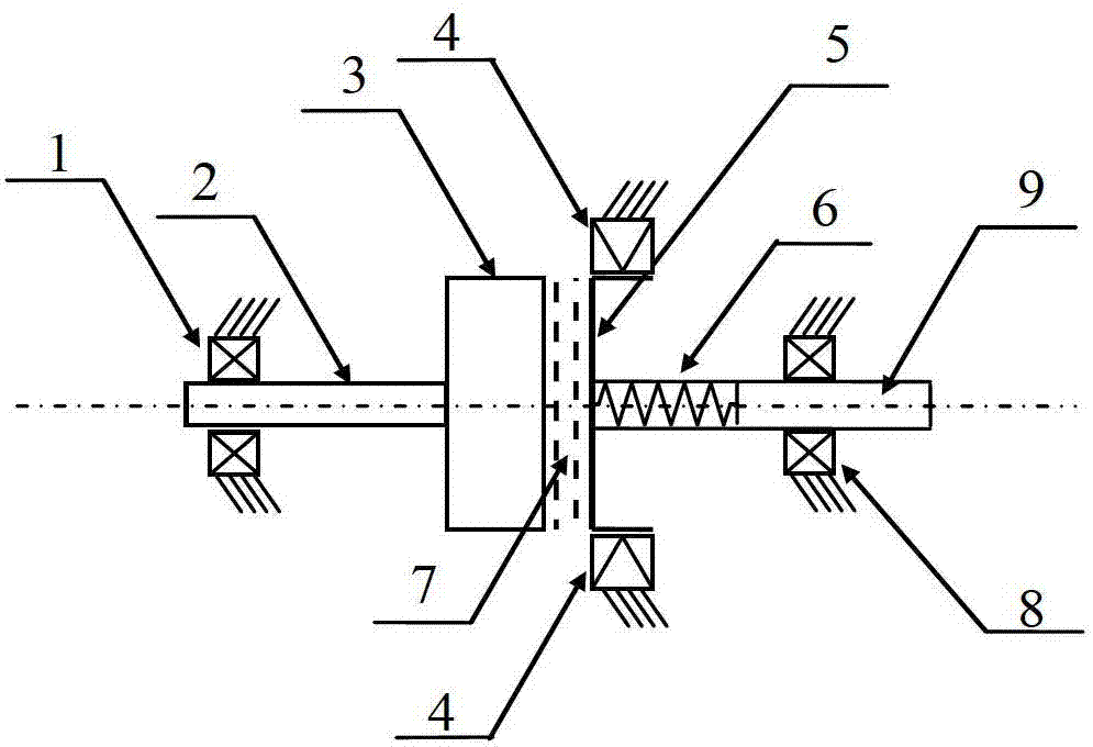
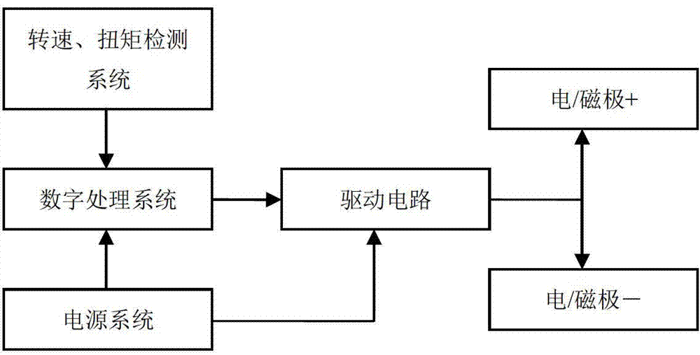
[0039] like figure 1 As shown, a stepless speed regulator includes an input system, a transmission system and an output system arranged coaxially and in series. The input system includes an input shaft locating bearing 1, an input shaft 2 and an energy storage flywheel 3, the variable speed transmission system includes a medium 7, a transmission disc 5 and a ratchet 4, and the output system includes a torsion spring 6, an output shaft locating bearing 8 and output shaft 9. Medium 7 is electrorheological fluid.

[0040] The input shaft locating bearing 1 is embedded with the input shaft 2 for fixing the input shaft 2 ; the output shaft locating bearing 8 is embedded with the output shaft 9 for fixing the output shaft 9 .

[0041]The input shaft 2 is rigidly connected with the energy storage flywheel 3 coaxially. The medium 7 is placed between the energy storage flywheel 3 and the transmission disc 5. When a voltage is applied, the medium 7 will solidify, thereby connecting t...

Embodiment 2

[0048] The medium 7 is an electromagnetic variable fluid, and the others are the same as in Embodiment 1. The surface of the energy storage flywheel 3 and the transmission disc 5 is treated with magnetic isolation.

Embodiment 3

[0050] The medium 7 is a controllable magnetic powder, and the others are the same as in the first embodiment.


PUM


Abstract

The invention discloses a stepless speed controlling method and a stepless speed controller. According to the method, a medium serves as a high-frequency transmission switch, conversion between the output revolving speed and the torque is achieved through a mechanical energy storage mechanism, the medium is subjected to solid and liquid transformation under the effect of voltage or a magnetic field, the mechanical energy storage mechanism is composed of a heavy energy storage flywheel and a light transmission disk, the medium is located between the energy storage flywheel and the transmission disk, when the voltage or the magnetic field is applied, the medium is solidified, the energy storage flywheel and the transmission disk are connected into a whole, when the voltage or the magnetic field disappears, the medium is liquefied, no mechanical connection exists between the energy storage flywheel and the transmission disk, the energy storage flywheel and the transmission disk rotate freely and separately, and the output revolving speed and the torque are controlled through controlling of the ratio of the solid state time of the medium to the liquid state time of the medium. The stepless speed controller which implements the method has the advantages of being wide in speed regulating time, fast in reaction, simple in structure, stable in output power and the like.

Description

technical field [0001] The invention relates to the field of electromechanical integration, in particular to a stepless speed regulation method and a stepless speed regulator. Background technique [0002] Generally, AC motors have a wide range of speed adjustment under frequency conversion speed regulation, but the power cannot be well utilized, especially when the frequency reduction speed regulation is generally constant torque output, the power loss is very large. The stepless speed controller better satisfies the good match between the electric motor and the transmission system under the optimal working condition. Traditional stepless speed regulators are mainly divided into hydraulic transmission, mechanical transmission and electric transmission. Hydraulic transmission has high requirements on the manufacturing precision of the governor, the price is relatively expensive, the output characteristic is constant torque, the slip rate is large, and oil leakage is prone t...

Claims


Application Information

Patent Timeline
Patent Type & Authority Patents(China)
IPC IPC(8): F16D37/00F16D48/06F16H49/00
Inventor 陈润恩闫国琦
Owner SOUTH CHINA AGRI UNIV
Why Eureka
Try Eureka