Plane solid high-voltage switch

A high-voltage switch, solid technology, applied in electrical components, spark gaps, spark gap components and other directions, can solve the problem of unstable performance of gas-insulated high-voltage switches, and achieve easy integration, fewer processes, and improved safety and reliability. sexual effect

Inactive Publication Date: 2013-02-27
BEIJING INSTITUTE OF TECHNOLOGYGY
View PDF4 Cites 10 Cited by
  • Summary
  • Abstract
  • Description
  • Claims
  • Application Information

AI Technical Summary

Problems solved by technology

[0005] The invention provides a planar solid high-voltage switch to solve the problem of unstable performance of gas-insulated high-voltage switches

Method used


Image

  • Plane solid high-voltage switch
  • Plane solid high-voltage switch
  • Plane solid high-voltage switch

Examples


Embodiment 1

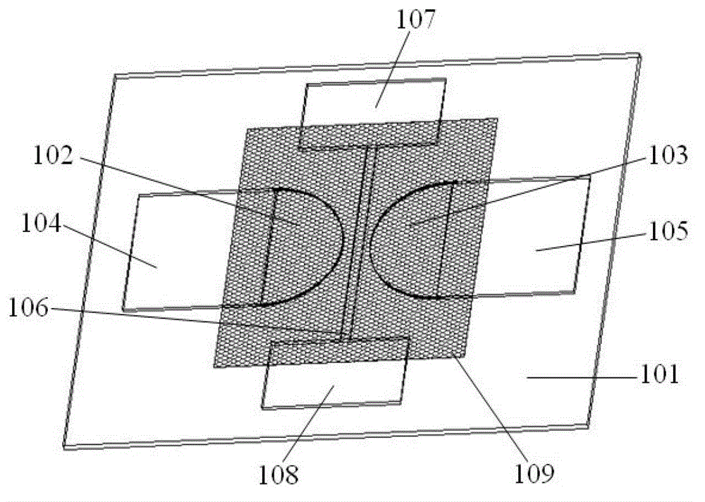
[0035] refer to figure 1 , showing a schematic diagram of a planar solid high voltage switch of the present invention, this embodiment may specifically include:

[0036] Insulating substrate 101, positive electrode 102, negative electrode 103, positive electrode welding plate 104, negative electrode welding plate 105, trigger electrode 106, trigger electrode welding plate 107, trigger electrode welding plate 108 and insulating layer 109;

[0037] Wherein, the positive electrode 102, the negative electrode 103, the positive electrode welding plate 104, the negative electrode welding plate 105, the trigger electrode 106, the trigger electrode welding plate 107 and the trigger electrode welding plate 108 are located on the surface of the insulating base 101, and the insulating layer 109 covers the positive electrode. Electrode 102, negative electrode 103 and trigger electrode 106 between positive electrode 102 and negative electrode 103; Positive electrode welding plate 104 is co...

Embodiment 2

[0050] refer to Figure 4 , shows the application circuit diagram of the planar solid high-voltage switch of the present invention, and this embodiment may specifically include:

[0051] Insulating substrate 401, positive electrode 402, negative electrode 403, positive electrode welding plate 404, negative electrode welding plate 405, trigger electrode 406, trigger electrode welding plate 407, trigger electrode welding plate 408, insulating layer 409 and the capacitor connected when the switch is in use 410. Trigger the power supply 411 and the electronic switch 412.

[0052] Wherein, the positive electrode 402, the negative electrode 403, the positive electrode welding plate 404, the negative electrode welding plate 405, the trigger electrode 406, the trigger electrode welding plate 407 and the trigger electrode welding plate 408 are located on the surface of the insulating base 401, and the insulating layer 409 covers the positive electrode. Electrode 402, negative electrod...


PUM


Abstract

The invention discloses a plane solid high-voltage switch for solving the unstable performance problem of the gas insulated high-voltage switch. The plane solid high-voltage switch comprises an insulating substrate, a positive electrode, a positive electrode welding plate, a negative electrode, a negative electrode welding plate, a trigger electrode, two trigger electrode welding plates and an insulating barrier, wherein the positive electrode, the positive electrode welding plate, the negative electrode, the negative electrode welding plate, the trigger electrode and the trigger electrode welding plates are positioned on the surface of the insulating substrate; the insulating barrier covers the positive electrode, the negative electrode and the trigger electrode positioned therebetween; the positive electrode welding plate and the positive electrode are connected; the negative electrode welding plate and the negative electrode are connected; and the two trigger electrode welding plates are connected with two ends of the trigger electrode. The safety and the reliability of the switch during use are improved.

Description

technical field [0001] The invention relates to a planar solid high voltage switch. Background technique [0002] At present, the three-dimensional gas spark gap switch and vacuum switch are based on traditional machining. Compared with the vacuum switch, the working voltage range of the gas switch is more limited. Generally, the working voltage of the gas switch is not greater than its static breakdown voltage (SBV , Static breakdown voltage) 80% -90%, when the operating voltage is lower than 50% of the static breakdown voltage, the switch is not reliable. The manufacturing process of the vacuum switch is much more complicated than that of the gas switch, because the vacuum switch has particularly strict requirements on the vacuum degree. If there is residual gas or pollutants inside, the impact on the vacuum switch is more obvious. Therefore, the vacuum switch electrode material needs to undergo fine degassing treatment, and its production cost is relatively high. [000...

Claims


Application Information

Patent Timeline
Patent Type & Authority Applications(China)
IPC IPC(8): H01T1/00H01T1/22H01T21/00
Inventor 曾庆轩吕军军李明愉
Owner BEIJING INSTITUTE OF TECHNOLOGYGY
Why Eureka
Try Eureka