S-PIN-diode-based directional diagram reconfigurable disk microstrip antenna

A technology of S-PIN and microstrip antenna, which is applied in the field of plasma technology and microstrip antenna, can solve the problem of solid-state plasma antenna or blank, and achieve the effect of large beam controllable range, large volume and small volume

Inactive Publication Date: 2013-03-06
SOUTH CHINA UNIV OF TECH
View PDF2 Cites 35 Cited by
  • Summary
  • Abstract
  • Description
  • Claims
  • Application Information

AI Technical Summary

Problems solved by technology

At present, the vast majority of research is limited to gaseous plasma antennas, and the research on solid-state plasma antennas is almost blank.

Method used


Image

  • S-PIN-diode-based directional diagram reconfigurable disk microstrip antenna
  • S-PIN-diode-based directional diagram reconfigurable disk microstrip antenna
  • S-PIN-diode-based directional diagram reconfigurable disk microstrip antenna

Examples


Embodiment Construction

[0017] The present invention will be described in further detail below in conjunction with the accompanying drawings, but the embodiments and protection of the present invention are not limited thereto.

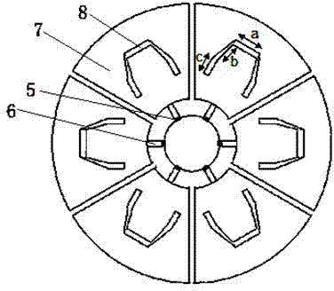
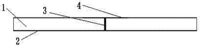
[0018] like figure 1 , figure 2 As shown, the pattern reconfigurable disk microstrip antenna adopts the coaxial feeding method. The main body includes a circular substrate 1, a ground plate 2, and the coaxial probe 3 is directly connected to the circular patch 4 for feeding. Six S-PIN diodes 5 are evenly installed on the edge of the circular patch 4, and the P-type end of each S-PIN diode is connected to the edge of the circular patch; the N-type end is connected to the fan-shaped parasitic patch through a rectangular microstrip line 6 And the width of the N-type terminal is consistent with the width of the rectangular microstrip line; each of the fan-shaped parasitic patches has a U-shaped slot; when the S-PIN diode is applied with a forward bias voltage, the S-PIN diode i...


PUM


Abstract

The invention discloses an S-PIN-diode-based directional diagram reconfigurable disk microstrip antenna, which comprises a circular patch for generating primary radiation and six fan-shaped parasitic patches with special U-shaped slots. An S-PIN diode is arranged between the circular patch and each parasitic patch, and the turning-on and turning-off states of each S-PIN diode are controlled by controlling the bias voltage of the S-PIN diode. When the antenna works, a probe is connected with the circular patch for direct feed, and is connected with one parasitic patch through the corresponding S-PIN diode, so that surface current flows towards the patch, and a directional diagram can be deflected towards the direction. The directional diagram can be scanned in all directions by sequentially conducting adjacent S-PIN diodes. The antenna is small in size, easy to integrate and wide in application range, works within the frequency bands of 802.11g and 802.11p, and has broad application prospect, and the directional diagram can be scanned in all directions.

Description

technical field [0001] The invention relates to solid-state plasma technology and microstrip antenna technology, in particular to a microstrip antenna that utilizes solid-state plasma technology to realize reconfigurable pattern. Background technique [0002] The rapid development of modern large-capacity, multi-functional, ultra-broadband integrated information systems has increased the number of information subsystems carried on the same platform. The number of antennas, which serve as channels for information in and out of wireless systems, has increased accordingly. The reconfigurable antenna technology enables the antenna to reconfigure the antenna characteristics in real time according to the actual environment, which has the advantages of reducing the overall cost of the integrated information system, reducing the weight, reducing the radar cross section of the system, and achieving good electromagnetic compatibility characteristics. Among them, the pattern reconfigu...

Claims


Application Information

Patent Timeline
Patent Type & Authority Applications(China)
IPC IPC(8): H01Q25/00H01Q9/04H01Q13/08H01Q3/34
Inventor 胡斌杰张家乐
Owner SOUTH CHINA UNIV OF TECH
Why Eureka
Try Eureka