Optical device for laser beam wave-front correction and wave-front correction method

A laser beam and optical device technology, applied in the laser field, achieves the effects of less laser absorption, low cost, and increased dynamic range of wavefront correction

Inactive Publication Date: 2013-03-06
11TH RES INST OF CHINA ELECTRONICS TECH GROUP CORP
View PDF4 Cites 11 Cited by
  • Summary
  • Abstract
  • Description
  • Claims
  • Application Information

AI Technical Summary

Problems solved by technology

[0006] The present invention provides an optical device for laser beam wavefront correction and a laser beam wavefront correction method to solve the above-mentioned problems in the prior art

Method used


Image

  • Optical device for laser beam wave-front correction and wave-front correction method
  • Optical device for laser beam wave-front correction and wave-front correction method
  • Optical device for laser beam wave-front correction and wave-front correction method

Examples


Embodiment Construction

[0032] Exemplary embodiments of the present disclosure will be described in more detail below with reference to the accompanying drawings. Although exemplary embodiments of the present disclosure are shown in the drawings, it should be understood that the present disclosure may be embodied in various forms and should not be limited by the embodiments set forth herein. Rather, these embodiments are provided for more thorough understanding of the present disclosure and to fully convey the scope of the present disclosure to those skilled in the art.

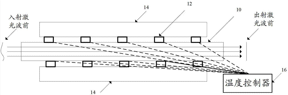
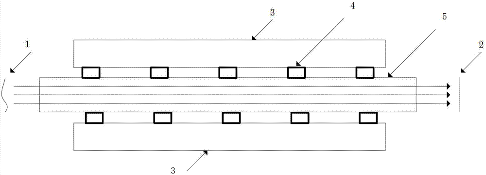
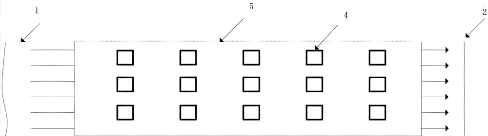
[0033] The invention provides an optical device and a laser beam wavefront correction method for laser beam wavefront correction. The array heat source is loaded on the surface of the optical material, and various temperature field distributions will be formed inside the optical material after the temperature is balanced. When the laser beam passes through this optical material, its wavefront will change, and controlling this change...


PUM


Abstract

The invention discloses an optical device for laser beam wave-front correction and a laser beam wave-front correction method. The optical device comprises an optical material, temperature controlling units, a radiating device and a temperature controller, wherein the optical material is used for receiving laser beams emitted from a laser gain medium through one end face, and emitting laser beams from another end face or emitting from the end face for receiving laser beams; theeach temperature control unit is used for heating or cooling under the control of the temperature controller; the radiating device is used for dissipating waste heat generated by the temperature control unit(s) when the temperature controller is used for controlling the temperature control unit(s) to cool; and the temperature controller is used for controlling the one or more temperature control units to heat or cool and controlling the heating amount or cooling amount of the one or more temperature control units, so as to control the temperature of laser beams on a path in the optical material and correct the wave-front of laser beams emitted into the optical material.

Description

technical field [0001] The invention relates to the field of laser technology, in particular to an optical device for correcting the wavefront of a laser beam and a method for correcting the wavefront of the laser beam. Background technique [0002] At present, in the development of high-power solid-state lasers, in addition to the need to increase power / energy, it is also necessary to study beam control and improve beam quality. Lasers with high power and high beam quality can meet the needs of practical applications. In actual work, the laser output by a high-power laser system has amplitude modulation and phase distortion. Both theoretical and experimental studies have proved that phase distortion is the main influencing factor for the quality of far-field beams. After the laser beam passes through a laser gain medium with a certain temperature distribution or a non-ideal optical system, its wavefront will be distorted, and this wavefront distortion will usually become mo...

Claims


Application Information

Patent Timeline
Patent Type & Authority Applications(China)
IPC IPC(8): H01S3/13
Inventor 刘磊刘洋王超刘刚梁兴波王文涛唐晓军赵鸿
Owner 11TH RES INST OF CHINA ELECTRONICS TECH GROUP CORP
Why Eureka
Try Eureka