
Longitudinal connection method for steel-concrete combined beam and existing reinforced concrete T beam

A reinforced concrete and composite beam technology, which is applied in bridges, bridge maintenance, bridge reinforcement, etc., can solve problems restricting the application of steel-concrete composite beams, complex structure and construction, etc., and achieve light lifting weight, fast installation speed, and realization of bending Effects of Moment and Shear Transmission

Active Publication Date: 2015-03-04
TSINGHUA UNIV
View PDF0 Cites 0 Cited by
  • Summary
  • Abstract
  • Description
  • Claims
  • Application Information

AI Technical Summary

Problems solved by technology

[0005] The traditional longitudinal connection method of steel-concrete composite beams and existing reinforced concrete T-beams usually adopts the embedded steel type, but this method is not only complicated in structure and construction, but also only suitable for the connection of steel-concrete composite beams and cast-in-place concrete beams At present, there is still a lack of mature methods to realize the reliable longitudinal connection between composite beams and existing reinforced concrete T-beams, which restricts the application of steel-concrete composite beams in the reinforcement and reconstruction of reinforced concrete T-beam bridges

Method used


Image

  • Longitudinal connection method for steel-concrete combined beam and existing reinforced concrete T beam
  • Longitudinal connection method for steel-concrete combined beam and existing reinforced concrete T beam
  • Longitudinal connection method for steel-concrete combined beam and existing reinforced concrete T beam

Examples


Embodiment Construction

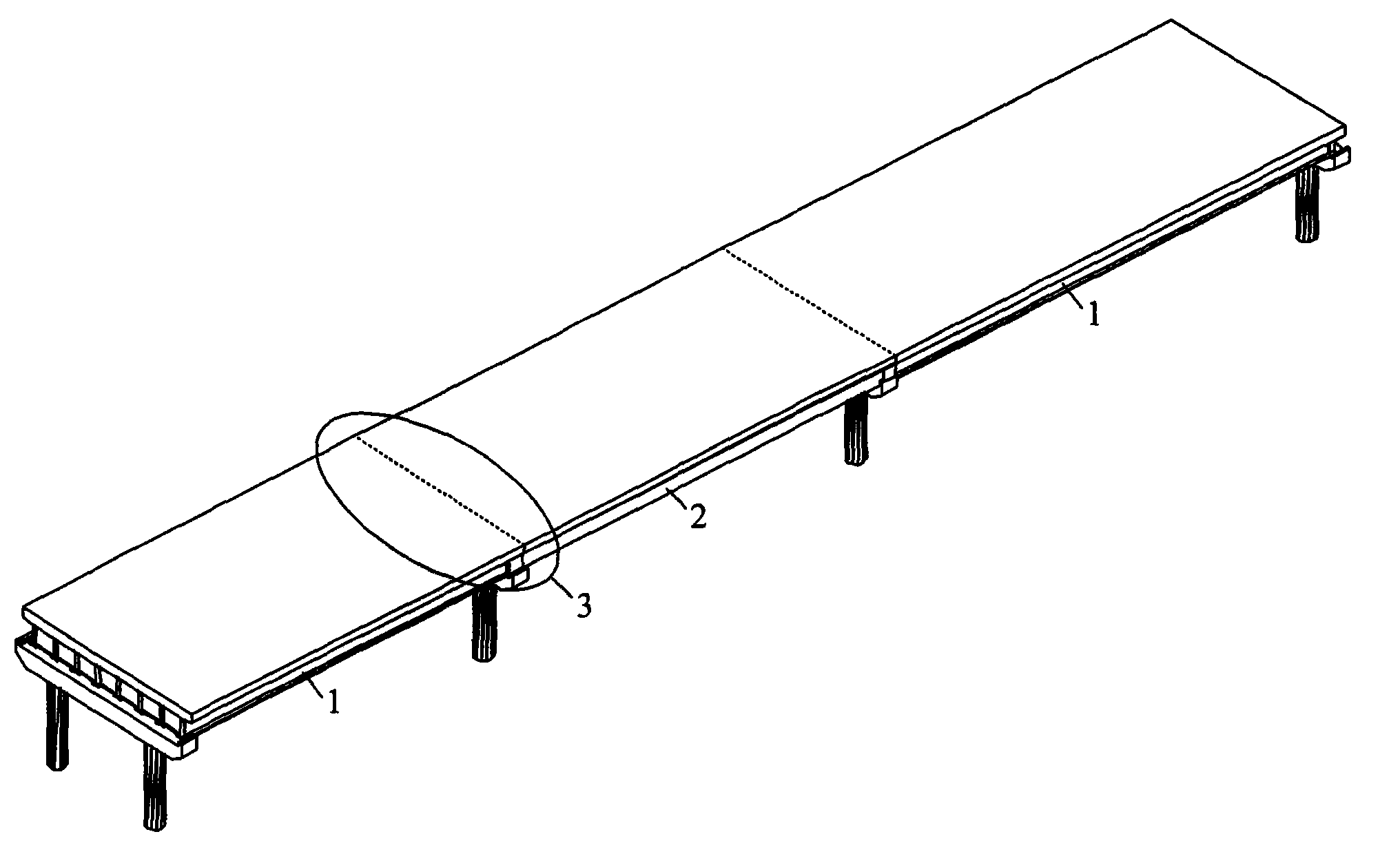
[0027] The structure, processing and use of the present invention will be further described below in conjunction with the accompanying drawings.

[0028] figure 2 Shown is the overall schematic diagram of the present invention. The specific construction steps are as follows:

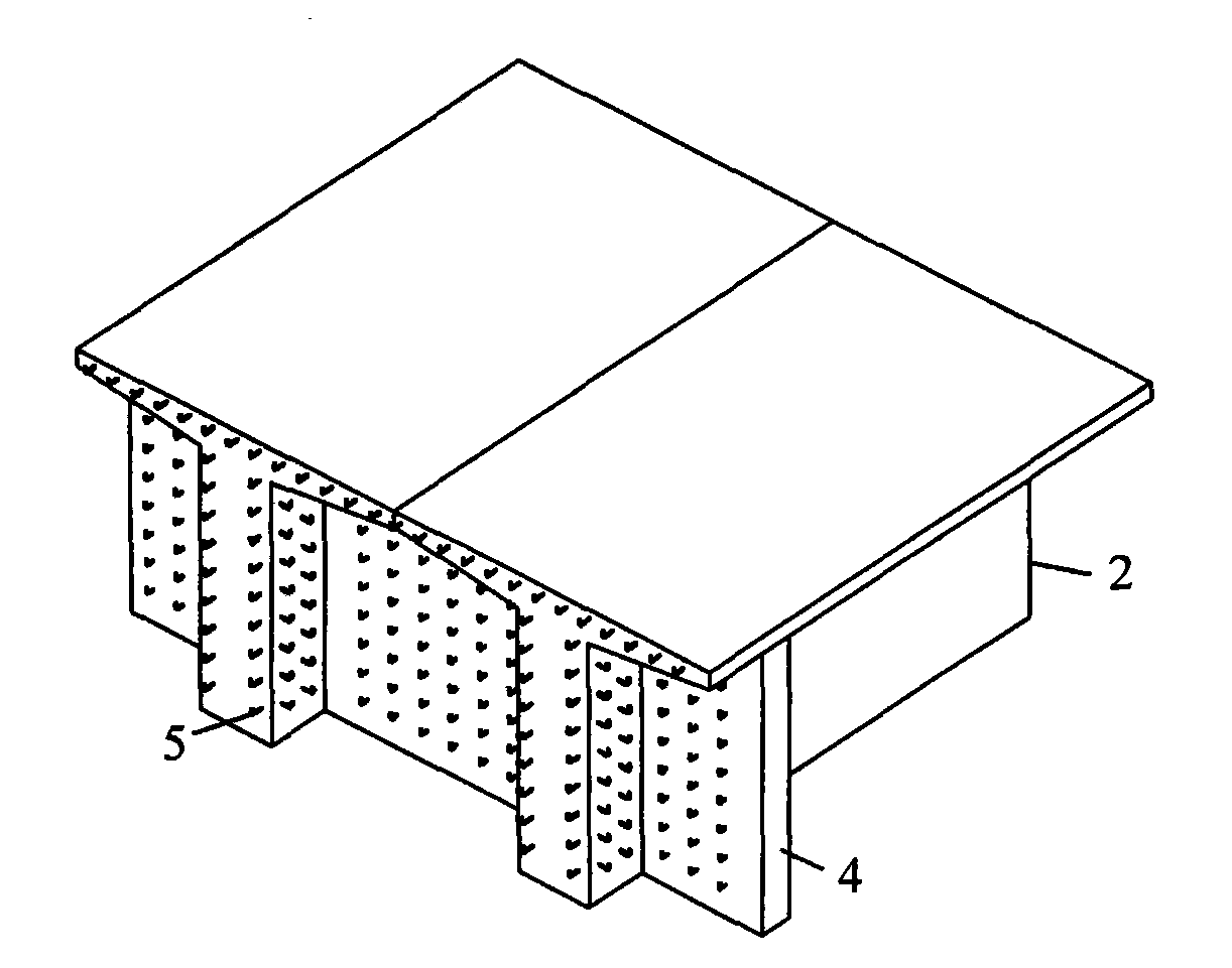
[0029] 1) Chiseling rough on the top surface of the original reinforced concrete T beam 2. The outer surface of the end of the original reinforced concrete T beam 2 and the outer surface of the original reinforced concrete T beam end partition 4 are chiseled, and L-shaped short steel bars 5 are planted in the chiseled place, such as image 3 shown;

[0030] 2) Make the steel structure part of the node area, such as Figure 4 shown. Firstly, steel girders are made. The height of the steel girder is the same as the height of the web plate of the original reinforced concrete T-beam 2. The transverse spacing between two adjacent webs of the steel beam 1 is the same as that of the original reinforced co...


PUM


Abstract

The invention relates to a longitudinal connection method for a steel-concrete combined beam and an existing reinforced concrete T beam, which can be used for reinforcing and reconstructing the existing reinforced concrete T beam, and belongs to the technical field of bridge engineering. The method comprises the following steps: one end part of the original reinforced concrete T beam is roughened, and bars are planted at the roughened part of the original reinforced concrete T beam; a node area steel structure part at which stud connectors are welded is processed, and a node area steel structure is mounted so as to enable a node area to form a box-shaped closed space; concrete is poured into the box-shaped closed space; steel bars of a concrete bridge deck slab are bound and longitudinal prestressed bars of the bridge deck slab are paved; concrete of the bridge deck slab in the node area is continuously poured; and longitudinal prestress of the bridge deck slab is stretched. The method disclosed by the invention overcomes deficiencies of a traditional connection method, and has the advantages of simple structure, prefabrication and assembly, rapidity and facilitation of the construction, small wet work amount of the concrete and little influence on the surrounding environment. Connecting nodes have good mechanical performance, reliable force transmission, high bearing capacity and good ductility; and meanwhile, the concrete is wrapped outside a steel plate, so that concrete gaps in the node area are avoided form being exposed outwards. The method disclosed by the invention has great generality and wide application prospect.

Description

technical field [0001] The invention relates to a longitudinal connection method of a steel-concrete composite beam and an existing reinforced concrete T beam, belonging to the technical field of bridge engineering. Background technique [0002] In recent years, due to a series of natural factors such as material aging and environmental erosion, human factors such as design errors, improper construction, overloading, etc., changes in structural functions, increased load levels, and other reasons, as well as improvements in design specifications and safety reserves, a large number of existing There are bridges that cannot meet the requirements of normal use in whole or in part, and need to be reinforced, reconstructed or repaired. [0003] Steel-concrete composite structure bridges have developed rapidly in the past 20 years. Due to their rational use of material characteristics and full use of their respective advantages, compared with pure steel structure bridges, it can gr...

Claims


Application Information

Patent Timeline
Patent Type & Authority Patents(China)
IPC IPC(8): E01D22/00
Inventor 聂建国陶慕轩杨悦樊健生
Owner TSINGHUA UNIV
Learn More