
Crank case ventilation electronic control method and system

A technology of crankcase ventilation and electronic control, which is applied in crankcase ventilation, machines/engines, mechanical equipment, etc. It can solve problems such as high idle speed, difficult adjustment, and failure to reach crankcase pressure, etc., and achieve the effect of preventing engine oil from deteriorating

Active Publication Date: 2015-07-22
HANGZHOU BRANCH ZHEJIANG GEELY AUTOMOBILE RES INST +2
View PDF8 Cites 0 Cited by
  • Summary
  • Abstract
  • Description
  • Claims
  • Application Information

AI Technical Summary

Problems solved by technology

This type of PCV valve has the following disadvantages: 1. The operating characteristic parameters of the plunger type PCV valve should be determined according to the comprehensive requirements of factors such as various engine operating conditions and the amount of blow-by gas in the crankcase under each operating condition, and the calculation and design of the flow characteristics are not accurate enough. lead to more difficult design
2. It is difficult to make accurate and timely adjustments according to different working conditions of the car, and cannot meet the technical requirements of the ideal crankcase pressure under all working conditions
3. The PCV valve is easy to wear and cause air leakage, resulting in excessive idle speed and unstable speed.
4. It is easy to freeze in winter and cause stuck faults

Method used


Image

  • Crank case ventilation electronic control method and system
  • Crank case ventilation electronic control method and system
  • Crank case ventilation electronic control method and system

Examples


Embodiment Construction

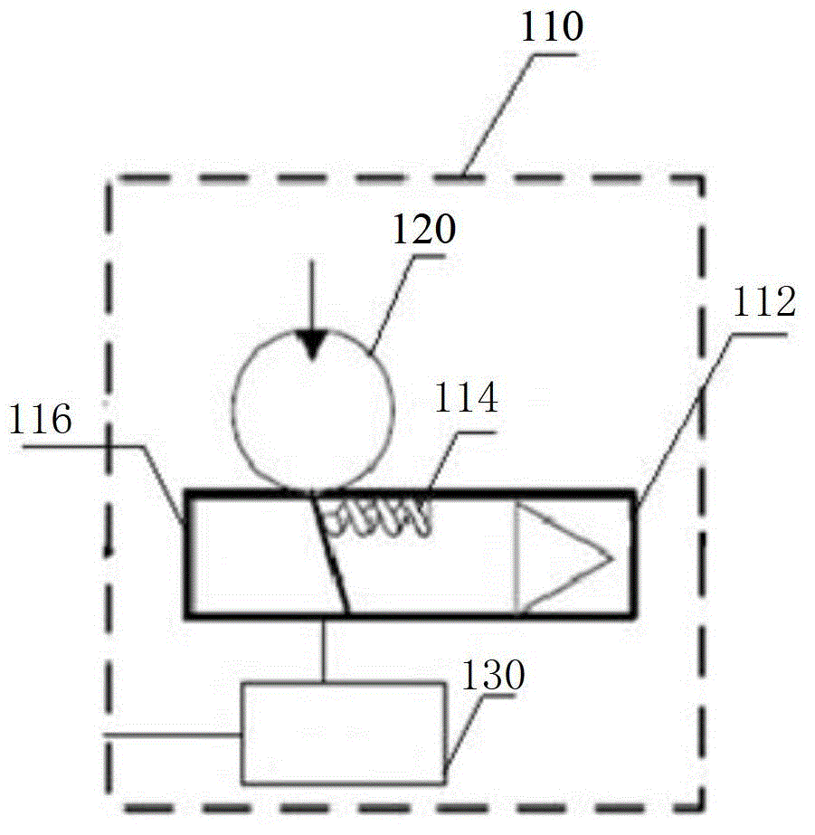
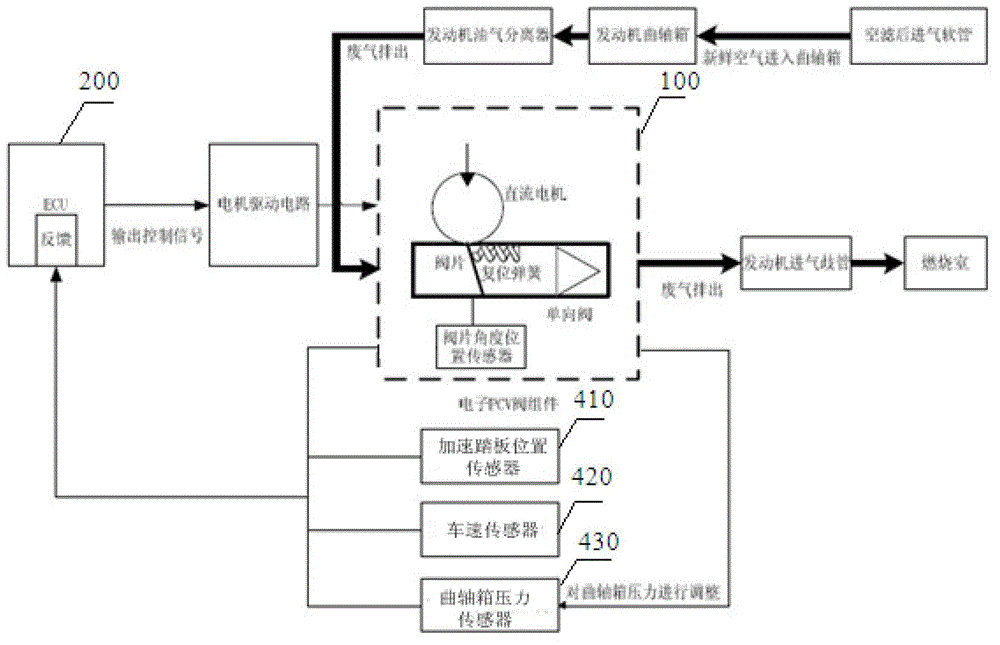
[0025] Such as figure 1 As shown, the present invention discloses an electronic PCV valve assembly 100, including a PCV valve 110, a DC motor 120 and a valve plate angular position sensor 130, the PCV valve 110 includes a valve 112 located on the air outlet of the valve body, and a valve located in the valve body The valve plate 114 and the return spring 116, the DC motor 120 and the return spring 116 are respectively connected with the valve plate 114, and the two cooperate to control the rotation of the valve plate 114 at a corresponding angle. The valve plate angle position sensor 130 is located on the valve plate 114 to monitor the valve plate 114 Sheet 114 deflects the angle.

[0026] The motor 120 will generate a corresponding torque under external control and apply it to the rotating shaft of the valve plate. When the torque generated by the motor 120 is equal to the tension value provided by the return spring 116, the valve plate 114 of the PCV valve 110 will be in a c...


PUM


Abstract

The invention discloses a crank case ventilation electronic control method, and the method comprises the following steps of (1) collecting internal pressure information of a crank case, and to be transmitteding the internal pressure information to an electronic control unit (ECU) to be processed so as to judge the pressure inside the crank case, continuing the step (1) if the pressure stays within the normal range, and entering a step (2) if the pressure exceeds the normal range; (2) an analysis and processing step, to be specific,: collecting information of a working state of a vehicle, transmitting the collected information to the ECU to be processed, adjusting the output current according to the working condition through the ECU, and controlling the openness of a valve plate of a pollution control valve (PCV); and (3) a feedback step, to be specific,: detecting the openness of the valve, transmitting the openness of the valve to the ECU to be processed, returning to the step (1) if the openness of the valve plate is identical to a preset value, and continuing the step (2) if the openness of the valve plate is not identical to the preset value. The real-time closed-loop control of an engine crank case ventilation system is realized by adopting an electronic control technology, so that the pressure of the crank case is maintained within a set range, and the pressure of the engine crank case is precisely controlled.

Description

technical field [0001] The invention belongs to the technical field of automobile electronics and relates to a crankcase ventilation control technology. Background technique [0002] The forced crankcase ventilation system, also known as the PCV system, is an essential device required by national mandatory regulations. When the engine is working, part of the combustible mixture and combustion products will escape from the cylinder to the crankcase through the piston ring. There may also be liquid fuel leaking into the crankcase when the engine is running at low temperatures. If these substances are not removed in time, it will accelerate the deterioration of the lubricating oil and cause the parts to be corroded or rusted. Again because contain HC, CO and other pollutants in the gas that escapes into the crankcase, according to national regulations: do not allow this harmful gas to be discharged into the atmosphere. The forced crankcase ventilation system used in modern a...

Claims


Application Information

Patent Timeline
Patent Type & Authority Patents(China)
IPC IPC(8): F01M13/00
Inventor 张久保吴汉涛马文亮李慧军由毅赵福全
Owner HANGZHOU BRANCH ZHEJIANG GEELY AUTOMOBILE RES INST
Learn More