
Method, optical module and system for extended field depth three-dimensional nanoscale-resolution imaging

A three-dimensional nano-imaging method technology, applied in optical components, optics, optical devices, etc., can solve the problems of small imaging depth, difficult to meet the requirements of molecular positioning and large depth of field, and achieve the effect of improving resolution

Active Publication Date: 2013-03-20
SHENZHEN UNIV
View PDF0 Cites 16 Cited by
  • Summary
  • Abstract
  • Description
  • Claims
  • Application Information

AI Technical Summary

Problems solved by technology

[0006] The purpose of the present invention is to provide a three-dimensional nano-resolution imaging method with a large depth of field, which aims to solve the problem that the traditional method has a small imaging depth and is difficult to meet the requirements of a large depth of field for molecular positioning

Method used


Image

  • Method, optical module and system for extended field depth three-dimensional nanoscale-resolution imaging
  • Method, optical module and system for extended field depth three-dimensional nanoscale-resolution imaging
  • Method, optical module and system for extended field depth three-dimensional nanoscale-resolution imaging

Examples


Embodiment 1

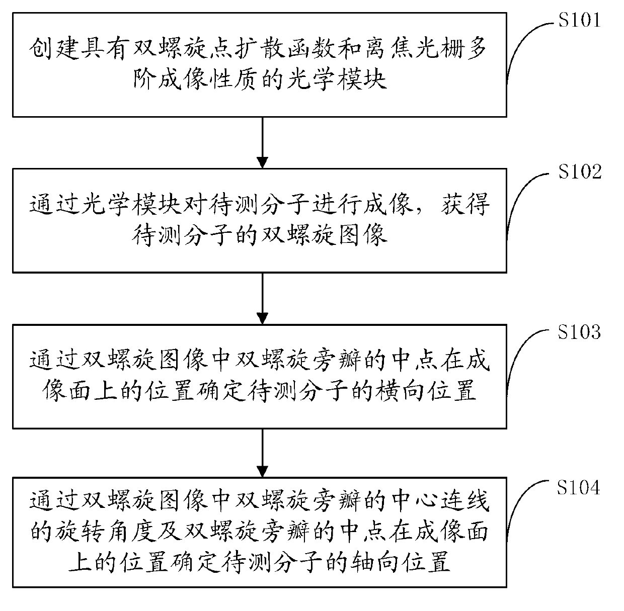
[0038] figure 1 A flow chart of the three-dimensional nano-resolution imaging method with a large depth of field provided by the first embodiment of the present invention is shown, and for convenience of description, only parts related to this embodiment are shown.

[0039] Reference attached figure 1 , the method mainly includes the following steps:

[0040] In step S101, create an optical module with double helix point spread function and defocused grating multi-order imaging properties;

[0041] In step S102, image the molecule to be tested through an optical module to obtain a double helix image of the molecule to be tested;

[0042] In step S103, the lateral position of the molecule to be measured is determined by the position of the midpoint of the side lobe of the double helix in the double helix image on the imaging plane;

[0043] In step S104, the axial position of the molecule to be measured is determined by the rotation angle of the line connecting the centers o...

Embodiment 2

[0074] Figure 9 A schematic diagram of an optical assembly for three-dimensional nano-resolution imaging with a large depth of field provided by the second embodiment of the present invention is shown. For convenience of description, only parts related to this embodiment are shown.

[0075] Based on the large depth-of-field three-dimensional nano-resolution imaging method provided in the above embodiments, this embodiment further provides an optical component that can be used for large depth-of-field three-dimensional nano-resolution imaging. This component is mainly used in a 3D imaging system to achieve a large depth of field and high-resolution 3D imaging of cells.

[0076] The optical assembly mainly includes a first lens 901 , an optical module 902 and a second lens 903 sequentially arranged along the transmission direction of the optical path. Among them, the optical module 902 has the above-mentioned double-helix point spread function and defocused grating multi-stage...

Embodiment 3

[0079] Figure 10 It shows a schematic diagram of a large depth of field super-resolution fluorescence microscopy imaging detection system provided by the third embodiment of the present invention, Figure 11 A schematic diagram of another large-depth-of-field super-resolution fluorescence microscopy imaging detection system provided by the third embodiment of the present invention is shown. For convenience of description, only parts related to this embodiment are shown.

[0080] An embodiment of the present invention provides a large depth of field super-resolution fluorescence microscopy imaging detection system based on the above-mentioned imaging method and optical components, combining the imaging method of the present invention with a super-resolution fluorescence microscopy imaging method (such as PALM, STORM), Realize ultra-large depth of field three-dimensional nano-resolution fluorescence microscopy imaging detection.

[0081] Such as Figure 10 The large depth of ...


PUM

PropertyMeasurementUnit
diameteraaaaaaaaaa

Abstract

The invention belongs to the technical field of microimaging and provides a method, an optical module and a system for extended field depth three-dimensional nanoscale-resolution imaging. The method comprises the following steps of 1, building the optical module having a double-helix point spread function and defocusing grating multistage imaging properties, 2, carrying out imaging of a molecule needing to be detected by the optical module to obtain a double-helix image, 3, determining a horizontal position of the molecule needing to be detected according to positions of middle points of double-helix sidelobes of the double-helix image, and 4, determining an axial position of the molecule needing to be detected according to a rotation angle of a connection line of centers of the double-helix sidelobes of the double-helix image, and the positions of the middle points of the double-helix sidelobes. Through combination of double effects of the double-helix point spread function and the defocusing grating multistage imaging, the method extends a field depth and improves a resolution ratio. The method can be used for dynamic range imaging of subcellular fractions having any depth values in a whole cell, can produce dynamic function images of multiple moving molecules, and has an important meaning for high-level understanding of a rule and a relationship between a subcellular structure and a cell function change.

Description

technical field [0001] The invention belongs to the technical field of microscopic imaging, and in particular relates to a three-dimensional nano-resolution imaging method with a large depth of field, an optical component and an imaging system. Background technique [0002] Cells are the basic unit of organisms and life activities. In-depth research on cells is the key to uncovering the mysteries of life, transforming life and conquering diseases. Carrying out molecular imaging under intact cells to obtain subcellular fine structures and even molecular maps, and obtaining information on these structural changes and molecular dynamic processes under living cells has always been an important direction of cytology research. At the same time, it is an urgent need for life sciences and a major challenge to imaging science to conduct nano-resolution three-dimensional structural and functional imaging of intact cells and to understand the relationship and regularity between subcell...

Claims


Application Information

Patent Timeline
Patent Type & Authority Applications(China)
IPC IPC(8): G01N21/64G01B11/00G02B21/36G02B27/22
CPCG01N21/47G01N21/6458G01N21/6447G01N21/6486G01N21/84G02B5/1842G02B5/189
Inventor 于斌陈丹妮牛憨笨李恒
Owner SHENZHEN UNIV
Learn More