Cutter track generating method based on potential energy field and energy functional optimization

An energy functional and generation method technology, applied in the field of milling, can solve the problems that cannot consider other constraints of energy distribution, such as line spacing control, cannot generate global smooth and stable line spacing distribution tool path, tool path shape and line spacing control optimization, etc.

Inactive Publication Date: 2013-03-20
武汉智能控制工业技术研究院有限公司
View PDF7 Cites 27 Cited by
  • Summary
  • Abstract
  • Description
  • Claims
  • Application Information

AI Technical Summary

Problems solved by technology

[0007] The processing areas such as blade machining and three-axis cavity machining may have arbitrary shapes or island distributions. The aforementioned existing methods cannot produce tool paths with global smooth and stable line spacing distribution. The reason is that the aforementioned algorithms all use bias The generation of contour lines is tran

Method used


Image

  • Cutter track generating method based on potential energy field and energy functional optimization
  • Cutter track generating method based on potential energy field and energy functional optimization
  • Cutter track generating method based on potential energy field and energy functional optimization

Examples


Embodiment Construction

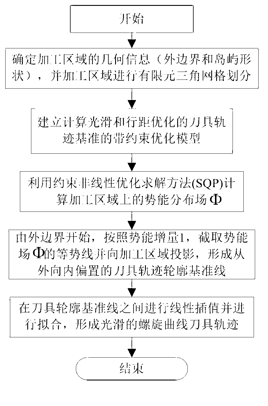
[0049] In order to make the object, technical solution and advantages of the present invention clearer, the present invention will be further described in detail below in conjunction with the accompanying drawings and embodiments. It should be understood that the specific embodiments described here are only used to explain the present invention, not to limit the present invention.

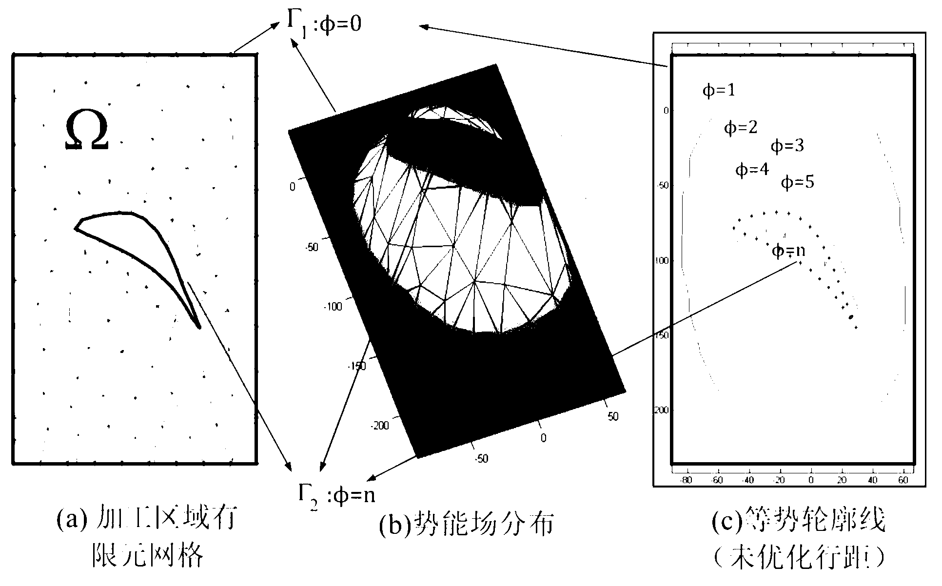
[0050] The present invention regards the processing area as a bounded surface domain and approximates it with a discrete triangular mesh, such as figure 2 As shown in (a), each node in the grid area has a certain potential energy value, thus forming a scalar potential energy field. If equal potential energy values ​​are assigned to the boundary of the processing area, and different boundaries have different equal potential energy values, since the scalar field is a continuous field, a continuously changing potential energy surface is formed in the entire processing area, as figure 2 As shown in ...


PUM


Abstract

The invention discloses a cutter track generating method based on a potential energy field and energy functional optimization. The cutter track generating method based on the potential energy field and the energy functional optimization comprises an energy functional, boundary conditions and line width constraint conditions. A method of finite elements is used to obtain a numerical approximation computational formula of a cutting track optimization calculating model, wherein the numerical approximation computational formula is based on a triangular discrete grid. An approximate value phi Phi on each node I where the potential energy field template Phi exists is obtained according to the cutter track calculating model. Contour lines of a volcanic vent are sectioned and images are cast on a machining zone omega Omega. Approximate tracks of equipotential contours are formed and smoothing and sampling are performed on the approximate tracks of the equipotential contours. Cutter track contour datum lines which are arranged from the exterior to the interior in an inclined mode are obtained. Linear interpolation is performed among the cutter track contour datum lines and a segment of a spiral cutter track is formed. All spiral cutter tracks are connected to form a spiral track. Curve fitting is performed on the spiral track to form a geometry second order continuous B spline cutter track. The cutter track generating method based on the potential energy field and the energy functional optimization achieves high-speed machining, optimizes cutting force distribution and improves quality of surface machining.

Description

technical field [0001] The invention belongs to the field of milling processing, and more specifically relates to a method for generating a tool trajectory path based on potential energy field and energy functional optimization. Background technique [0002] High-quality and efficient CNC machining requires that the tool paths generated by Computer Aided Manufacturing (CAM) have the characteristics of smoothness and uniform line spacing (that is, stable material removal rate). The curved tool path generated by the traditional parametric surface isoparametric or contour isometric offset method can effectively control the line spacing (including line cutting, ring cutting, etc.) to a certain extent, but its shape is severely restricted by the parameters of the processing area or Boundary shape, poor smoothness; the newly developed curve trajectory method such as helical line processing produces an equipotential contour line family similar to the electric potential field in the...

Claims


Application Information

Patent Timeline
IPC IPC(8): G05B19/41
CPCY02P70/10
Inventor 李振瀚颜昌亚田飞超杨建中
Owner 武汉智能控制工业技术研究院有限公司
Why Eureka
Try Eureka