Radio frequency identification (RFID) ultrathin metal-resisting electronic tag based on folded dipole

An electronic label and folded vibrator technology, applied to record carriers, instruments, computer parts, etc. used in machines, can solve the problems of inability to bend, thick size, and low sensitivity of metal surfaces, and achieve high flexibility, convenient production, Solve complex effects

Inactive Publication Date: 2013-03-20
王学祥
View PDF1 Cites 7 Cited by
  • Summary
  • Abstract
  • Description
  • Claims
  • Application Information

AI Technical Summary

Problems solved by technology

[0010] The purpose of the present invention is to provide an RFID ultra-thin anti-metal electronic tag based on a folding vibrator, so that it can effectively solve the problem of high cost and large size of anti-metal electronic tags in the prior art without using the above three methods. Thick, non-bendable, and low-sensitivity technical problems on metal surfaces

Method used


Image

  • Radio frequency identification (RFID) ultrathin metal-resisting electronic tag based on folded dipole
  • Radio frequency identification (RFID) ultrathin metal-resisting electronic tag based on folded dipole
  • Radio frequency identification (RFID) ultrathin metal-resisting electronic tag based on folded dipole

Examples


Embodiment 1

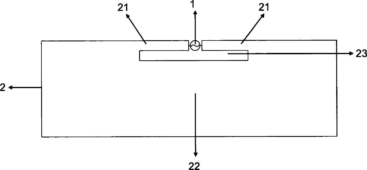
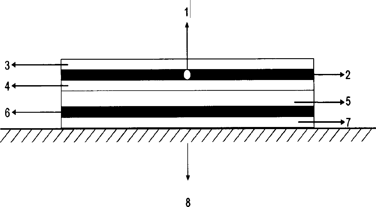
[0031] figure 1 figure 2 Shown is an ultra-thin plane anti-metal electronic tag based on a folded vibrator according to an embodiment of the present invention, wherein, figure 1 It is a schematic plan view of the electronic tag in Embodiment 1 of the present invention; figure 2 It is a schematic cross-sectional structure diagram of the electronic tag in Embodiment 1 of the present invention. Such as figure 1 and figure 2 As shown, the ultra-thin anti-metal electronic tag includes an ultra-high frequency RFID chip 1 and a radiator 2, the radiator 2 includes a feed loop gap 23, and the ultra-high frequency RFID chip 1 has a thin vibrator on one side of the feed loop gap 23 On the arm 21, there is a gap in the middle of the thin vibrator arm 21 for placing the UHF RFID chip 1. The thin vibrator arm 21 is electrically or capacitively connected to the UHF RFID chip 1. The feed loop gap 23 can be rectangular, Oval, trapezoidal or deformed structures, and the slot length of t...

Embodiment 2

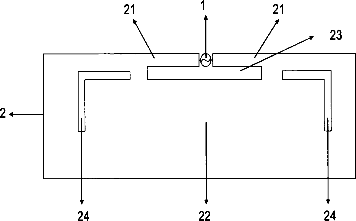
[0037] See image 3 , image 3 is a schematic diagram of the planar structure of the electronic tag in Embodiment 2 of the present invention; the structure of the electronic tag in this embodiment is the same as figure 1 Compared with the electronic tag in the shown embodiment 1, its general structure is similar, the cross-sectional structure schematic diagram in the embodiment 2 and the figure 2 Exactly the same, except that image 3 A frequency fine-tuning slit 24 is added to the radiator 2. Changing the size of the frequency fine-tuning slit 24 can play a role in adjusting the frequency, but it is not the main factor determining the performance of the label.

Embodiment 3

[0039] See Figure 4 , Figure 4 It is a schematic plan view of the electronic tag in Embodiment 3 of the present invention. The structure of the electronic tag in this embodiment is the same as image 3 Compared with the electronic tag in the shown embodiment 2, the radiator 2 increases the second feeding loop gap 231, and by changing the size of the second feeding loop gap 231, the electronic tag can be operated in two frequency ranges. Work to achieve the purpose of expanding the bandwidth of electronic tags. The schematic diagram of the cross-sectional structure in embodiment 3 and such as figure 2 The schematic diagrams of the cross-sectional structures in the shown embodiment 1 and embodiment 2 are completely the same.


PUM


Abstract

The invention discloses a radio frequency identification (RFID) ultrathin metal-resisting electronic tag based on folded dipole. Far distance reading can be achieved in a free space and a metal surface. The RFID ultrathin metal-resisting electronic tag based on the folded dipole comprises an ultra-high frequency RFID chip, a radiation body, an ultrathin insulation medium and a metal thin layer. The radiation body is of a folded dipole structure, or a multiple folded dipole structure or a deformed structure. A radiation surface is large in metal area, so that receiving capacity of the electronic tag can be improved, and effect of electromagnetic wave from metal reflection is shielded. The radiation body is not connected with the metal thin layer. A single-layer printing antenna without a through hole and a short circuit structure is adopted, and at the same time a complex structure like electroblepharogram (EBG) does not exist. The thickness of the electronic tag is wholly below 0.5mm. The RFID ultrathin metal-resisting electronic tag based on the folded dipole has high flexibility, can be directly pasted on a metal pipe and a packing bag containing the metal thin layer, and metal articles which have strict requirements for thickness and bending. The RFID ultrathin metal-resisting electronic tag based on the folded dipole is simple in manufacturing technology, and greatly reduces production cost.

Description

technical field [0001] The invention belongs to the field of wireless technology, and in particular relates to an ultra-thin anti-metal electronic tag that can be attached to a metal surface. Background technique [0002] Radio frequency identification is RFID (Radio Frequency IDentification) technology, which is a communication technology that can identify specific targets and read and write related data through radio signals without the need to establish mechanical or optical contact between the identification system and specific targets. RFID radio frequency identification technology has important applications in logistics management, anti-counterfeiting, production automation and intelligent transportation. [0003] A complete RFID system is generally composed of three parts: the reader (Reader), the electronic tag (TAG), the so-called transponder (Transponder) and the application software system. Its working principle is that the reader emits a specific The frequency o...

Claims


Application Information

Patent Timeline
Patent Type & Authority Applications(China)
IPC IPC(8): G06K19/077
Inventor 王学祥
Owner 王学祥
Why Eureka
Try Eureka