
Multi-tap composite excitation type controllable reactor

A technology of compound excitation and reactor, applied in the direction of variable inductors, inductors, variable transformers, etc., can solve the problems of reducing system reliability, complex control strategy, increasing loss, etc., to reduce noise, reduce harmonic Wave content and loss, and the effect of improving the response speed

Inactive Publication Date: 2015-06-03
ZHEJIANG UNIV +1
View PDF4 Cites 0 Cited by
  • Summary
  • Abstract
  • Description
  • Claims
  • Application Information

AI Technical Summary

Problems solved by technology

This method can effectively improve the response speed of the magnetic valve type controllable reactor, but this method needs to provide a separate magnetic power supply, and the external DC source is composed of two sets of rectification circuits, the cost is high, and the control strategy is complicated
And the rectifier circuit is connected in series with two sets of composite coils, which increases the loss and reduces the reliability of the system

Method used


Image

  • Multi-tap composite excitation type controllable reactor
  • Multi-tap composite excitation type controllable reactor
  • Multi-tap composite excitation type controllable reactor

Examples


Embodiment 1

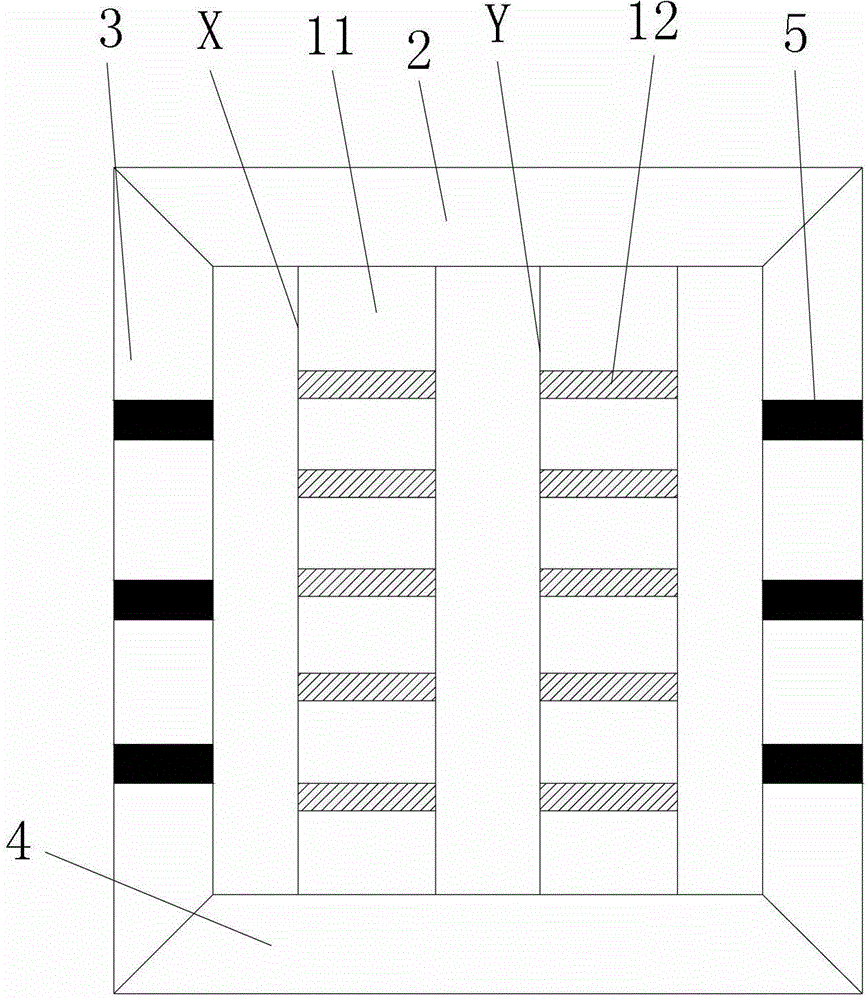
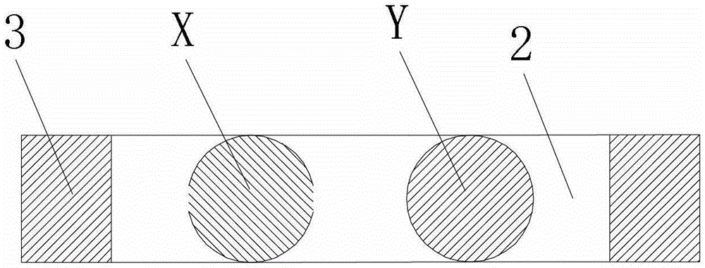
[0051] Such as figure 1 and figure 2 As shown, a multi-tap compound excitation type single-phase controllable reactor has a four-column structure; it includes: an upper yoke 2, a lower yoke 4, two side yokes 3, and a pair of iron cores (X, Y ), the iron core (X, Y) is divided into five sections of discus 11, and the discus 11 of adjacent sections is isolated by magnetic valve 12 (four pieces); the discus is formed by lamination of several silicon steel sheets;

[0052] The side yoke 3 is divided into four sections, and the adjacent sections are separated by air gaps 5 (three groups); the air gaps 5 are filled with epoxy resin, and the total thickness of the three groups of air gaps accounts for 5% of the height of the side yoke; It can prevent the nonlinearity of the reactor when the DC is no-load, so as to avoid the ferromagnetic resonance caused by the nonlinearity of the reactor.

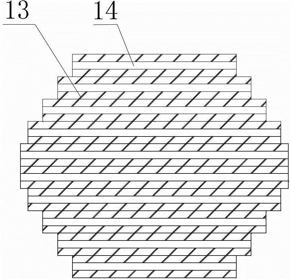
[0053] Such as image 3 As shown, the magnetic valve 12 is composed of a number of silico...

Embodiment 2

[0072] Such as Figure 6 and Figure 7 As shown, a multi-tap compound excitation type three-phase controllable reactor has a six-column structure; it includes: an upper yoke 2, a lower yoke 4, and three pairs of iron cores (X-X', Y -Y', Z-Z'), the iron core is divided into several sections of discus, and the adjacent discus sections are separated by magnetic valves; the discus is made of several silicon steel sheets;

[0073] The magnetic valve is composed of a number of silicon steel sheets and a number of epoxy resin sheets alternately stacked in the horizontal direction; the magnetic valves on the iron core are divided into four categories: magnetic valve A, magnetic valve B, magnetic valve C and magnetic valve D; among them:

[0074] The total area ratio of the magnetically conductive sheet and the magnetically resistive sheet in the cross section of the magnetic valve A is 1:2, and the total thickness of this type of magnetic valve accounts for 28% of the total thickness...


PUM

PropertyMeasurementUnit
thicknessaaaaaaaaaa
thicknessaaaaaaaaaa

Abstract

The invention discloses a multi-tap composite excitation type controllable reactor. The multi-tap composite excitation type controllable reactor comprises an upper yoke, a lower yoke and n pairs of iron cores arranged between the upper yoke and the lower yoke, wherein an upper set of windings and a lower set of windings are wound on the iron cores; each pair of iron cores comprises an iron core X and an iron core Y; windings on the iron cores X and windings on the iron cores Y are connected through a set of controllable components; each of the upper windings on the iron cores X is provided with two tap points; each of the lower windings on the iron cores X is provided with a tap point; each of the upper windings on the iron cores Y is provided with a tap point; and each of the lower windings on the iron core Y is provided with two tap points. In the controllable reactor, a high-voltage tap coil is added for each phase for composite excitation, and the coil positively adds magnetism, so that when the compensation capacitance is increased, the excitation strength can be increased and the response speed is increased; and meanwhile, in the controllable reactor, a reverse low-voltage tap coil is added for each phase for reverse excitation, and the coil plays the role of quickly reducing direct-current magnetic flux, so that when the required compensation capacitance is reduced, reverse direct-current magnetic flux can be formed, and the speed of reducing the direct-current excitation of the system is increased.

Description

technical field [0001] The invention belongs to the technical field of reactive power compensation, and in particular relates to a multi-tap compound excitation type controllable reactor. Background technique [0002] In recent years, with the acceleration of the development of my country's electric power industry, the demand for electric energy is also increasing. The reactive power in the power system is not directly used as the actual power consumption, but the conversion of reactive power will cause voltage rise and fall and power loss on power generation and transmission equipment. The unbalanced reactive power of the power grid will lead to huge fluctuations in the system voltage, and in severe cases, it will cause damage to electrical equipment and accidents such as system voltage collapse. Therefore, reactive power compensation technology is very necessary to improve the power quality of the power system and tap the potential of the power grid. [0003] At present,...

Claims


Application Information

Patent Timeline
Patent Type & Authority Patents(China)
IPC IPC(8): H01F29/02H01F27/40H01F27/30H01F27/24H02J3/18
CPCY02E40/30
Inventor 陈国柱王异凡张曙
Owner ZHEJIANG UNIV
Learn More