Voltage-type wireless power supply system load identification method

A technology of wireless power supply and load identification, applied in electromagnetic wave systems, circuit devices, electrical components, etc., can solve problems such as complex hardware circuits, complex control systems, and reduced reliability of energy transmission and wireless communication

Active Publication Date: 2013-03-20
重庆前卫无线电能传输研究院有限公司
View PDF4 Cites 20 Cited by
  • Summary
  • Abstract
  • Description
  • Claims
  • Application Information

AI Technical Summary

Problems solved by technology

[0003] However, these traditional identification technologies mainly use the phase difference between the primary side resonant voltage and current to identify the load. Too many variables need to be detected, which makes the control system very complicated and difficult to implement.
[0004] For a voltage-type IPT system, if a wireless communication module is used to realize load identification, due to the presence of high-frequency magnetic fields of power transmission and wireless communication at the same time, the mutual interference betw

Method used


Image

  • Voltage-type wireless power supply system load identification method
  • Voltage-type wireless power supply system load identification method
  • Voltage-type wireless power supply system load identification method

Examples


Embodiment Construction

[0053] The present invention will be described in further detail below in conjunction with the accompanying drawings and specific embodiments.

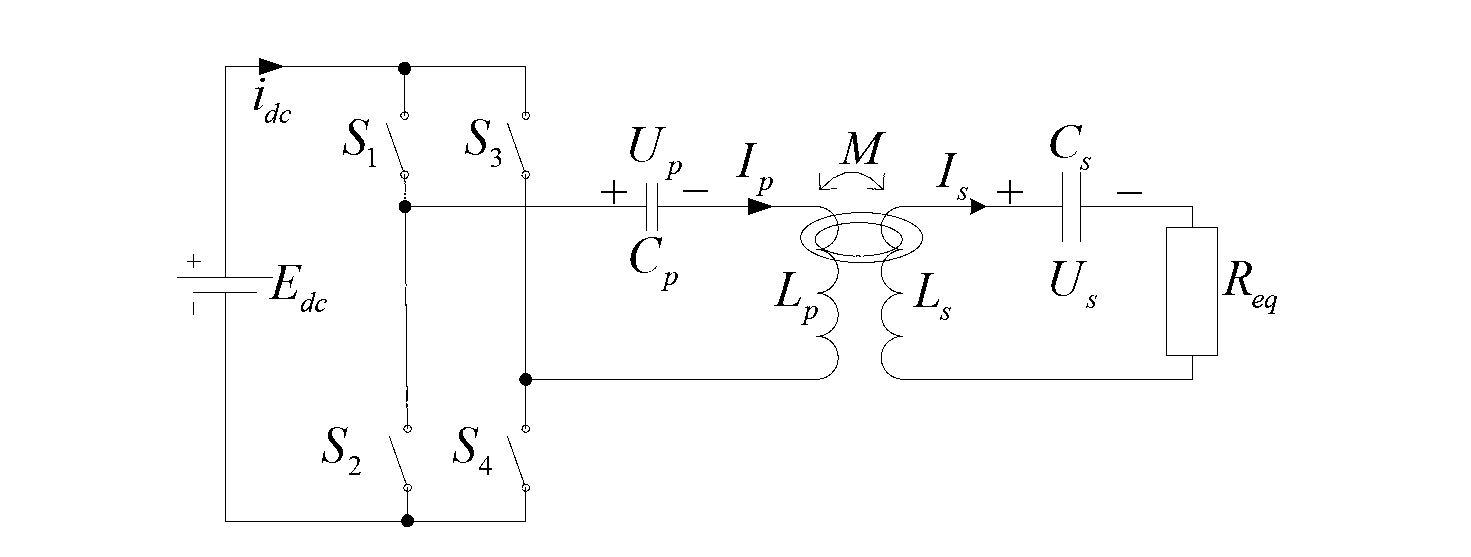
[0054] The voltage-type IPT system can be divided into two basic resonant topological structures, SS and SP. The present invention takes the SS structure as an example, as figure 1 as shown,

[0055] C in the picture p 、C s Respectively, the primary and secondary side resonant inductance L p , L s The compensation capacitance; M is the mutual inductance coupling value between the primary and secondary coils; i dc , I p and I s Respectively, the injection current of the inverter bridge, the primary side inductor resonant current and the secondary side resonant network current; U p , U s are the voltages across the primary and secondary compensation capacitors respectively; ω 0 , ω d Respectively, the natural frequency of the secondary resonant network and the system resonant operating frequency; R L is the load impedance. I...


PUM


Abstract

The invention discloses a voltage-type wireless power supply system load identification method. The voltage-type wireless power supply system load identification method comprises the following steps: establishing an inductively power transfer (IPT) system, a primary side circuit sampling circuit obtains 2N primary side resonance current peak values and system working frequency sampling values in a free resonance state and computes total active wear portion RX generated by a secondary side circuit. Whether a non-mutual-inductance-coupling value M exists or not can be judged by comparison of the RX with a primary side coil internal resistance value Rp. If the non-mutual-inductance-coupling value M exists, a load resistance value Re q can be computed. The voltage-type wireless power supply system load identification method has the obvious advantages of being capable of detecting changes of oscillation frequency and the primary side resonance current peak values in a period of a free resonance mode by utilizing two basic modes, namely energy filling and free resonance, and therefore whether load exists or not and power grades of the load when the load exists can be identified.

Description

technical field [0001] The invention belongs to a load identification technology of an IPT system, in particular to a load identification method of a voltage-type wireless power supply system. Background technique [0002] Inductively Power Transfer (IPT) technology is a new type of safe power supply technology based on Faraday's electromagnetic induction principle, which uses high-frequency alternating magnetic field to realize wireless transmission of electric energy between a completely electrically insulated power system and a movable load. This technology has been widely used in fields such as electric vehicles, rotating electrical equipment, biomedicine, home appliances and mobile electronic devices. Due to the large power nature and level span of the load carried by the IPT system (several milliwatts to thousands of watts), if the nature and power of the load are not identified, the stability and reliability of the IPT system will be greatly reduced. Therefore, befor...

Claims


Application Information

Patent Timeline
IPC IPC(8): H02J17/00H02J50/12
Inventor 王智慧孙跃苏玉刚唐春森戴欣
Owner 重庆前卫无线电能传输研究院有限公司
Why Eureka
Try Eureka