Deashing device for SCR flue gas denitration system

An ash cleaning device and denitrification technology, applied in the field of air pollutant control, can solve the problems of shortening the catalyst life, increasing the weight of the reactor, blocking the flow of flue gas, etc., so as to improve the overall economic benefit, reduce the operating cost, and increase the sedimentation rate. Effect

Inactive Publication Date: 2013-03-27
SHANDONG UNIV
View PDF5 Cites 12 Cited by
  • Summary
  • Abstract
  • Description
  • Claims
  • Application Information

AI Technical Summary

Problems solved by technology

Conventionally, most SCR reactors are chosen to be arranged after the boiler economizer. Due to the high concentration of fly ash in the flue gas, on the one hand, it is easy to cause wear, blockage and poisoning of the catalyst, shorten the life of the catalyst, and increase the operating cost; on the other hand, the reaction The lower elbow of the flue gas inlet section of the reactor is prone to ash accumulation, which blocks the flow of flue gas, increases the weight of the reactor, and even causes the shutdown of the reactor, resulting in huge losses

Method used


Image

  • Deashing device for SCR flue gas denitration system
  • Deashing device for SCR flue gas denitration system

Examples


Embodiment 1

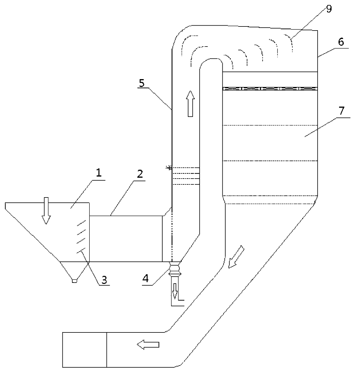
[0017] Ash cleaning device in SCR flue gas denitrification system ( figure 1 ), including the front ash hopper 1 and the catalyst bed 7, the catalyst bed 7 is placed in the shell 6, and the deflector 9 is arranged in the shell 6, and the front ash hopper 1 passes through the horizontal flue 2 and the ascending flue 5 It communicates with the shell 6, the ash baffle 3 is arranged at the junction of the front ash hopper 1 and the horizontal flue 2, the flue gas outlet of the economizer is connected with the front ash hopper 1, and the ascending flue 5 and the horizontal flue 2 The inner bottom of the junction is provided with an air-lock powder feeder 4 . The air-lock powder feeder 4 is connected with the dust collector through the pipeline, and the dust accumulation is regularly removed.

Embodiment 2

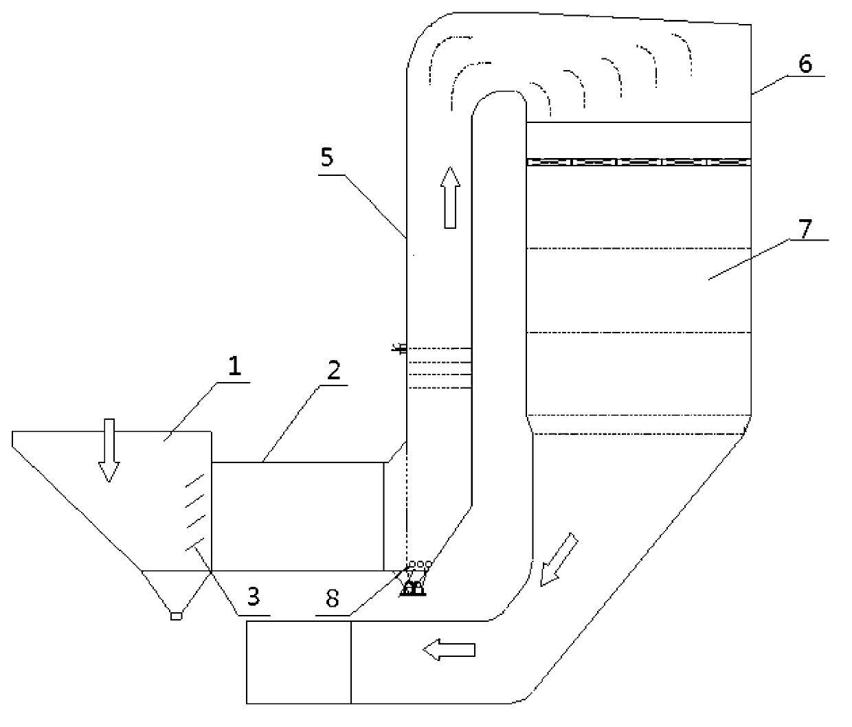
[0019] Ash cleaning device in SCR flue gas denitrification system ( figure 2 ), including the front ash hopper 1 and the catalyst bed 7, the catalyst bed 7 is placed in the shell 6, and the deflector 9 is arranged in the shell 6, and the front ash hopper 1 passes through the horizontal flue 2 and the ascending flue 5 It communicates with the shell 6, the ash baffle 3 is arranged at the junction of the front ash hopper 1 and the horizontal flue 2, the flue gas outlet of the economizer is connected with the front ash hopper 1, and the ascending flue 5 and the horizontal flue 2 A soot blowing pipe 8 is provided at the inner bottom of the junction. The soot blowing pipe 8 regularly blows soot, and the gas source is air or steam or a mixture of air and steam.

[0020] The cross-sectional size of the traditional ash hopper inlet is 8535mm×6620mm, and the cross-sectional size after expansion is 11945mm×9265mm; the size of the traditional horizontal flue is 3800mm×5800mm, and the cr...


PUM


Abstract

The invention relates to a deashing device for an SCR flue gas denitration system. The deashing device comprise a preposed ash bucket and a catalyst bed; the catalyst bed body is arranged in a shell; a guide plate is arranged in the shell; a flue gas outlet of an economizer is connected with the preposed ash bucket; the preposed ash bucket communicates with the shell through a horizontal flue, an uptake flue and the shell; an ash blocking plate is arranged on the joint of the preposed ash bucket and the horizontal flue; and an air-lock powder supply device or a gas blowing tube is arranged at an inner bottom end of the joint of the uptake flue and the horizontal flue. The device provided by the invention can effectively reduce abrasion, clogging and poisoning on the catalyst, caused by flue gas fly ash, increase service life of the catalyst and lower operating costs; on the other hand, the air-lock powder supply device or the gas blowing tube arranged at an elbow position of the horizontal flue can effectively remove dust accumulated in the device, ensure smoothness of the flue, reduce the weight of the device, ensure continuous operation of the system, and increase the overall economic benefits.

Description

technical field [0001] The invention belongs to the technical field of atmospheric pollutant treatment, and specifically relates to a device for effectively removing fly ash in the flue gas passing through the SCR flue gas denitrification system and ash accumulation in the device through various methods, so as to reduce the wear and blockage of the catalyst by the fly ash , to ensure long-term stable operation of the device. Background technique [0002] Since my country's "Twelfth Five-Year Plan" period has raised the emission standards for nitrogen oxides, most power plants currently use selective catalytic reduction (selective catalytic reduction, SCR) flue gas denitrification process for thermal power plant flue gas denitrification, in which the SCR reactor is The core equipment of SCR process. Conventionally, most SCR reactors are chosen to be arranged after the boiler economizer. Due to the high concentration of fly ash in the flue gas, on the one hand, it is easy to c...

Claims


Application Information

Patent Timeline
Patent Type & Authority Applications(China)
IPC IPC(8): B01D53/86B01D53/56B01D45/02B01D45/08F23J15/02
CPCY02A50/2351
Inventor 王志强王旭江马春元范燕荣
Owner SHANDONG UNIV
Why Eureka
Try Eureka