
Lifting roller displacement control device in plate rolling machine

A technology of displacement control and lifting rollers, which is applied in the field of displacement control devices for machine parts, can solve problems such as poor overload protection performance, low degree of automation, and inappropriate curvature of the coiling plate, and achieve good overload protection performance, high degree of automation, and simple operation Effect

Inactive Publication Date: 2013-03-27
西安兰石重工机械有限公司
View PDF0 Cites 3 Cited by
  • Summary
  • Abstract
  • Description
  • Claims
  • Application Information

AI Technical Summary

Problems solved by technology

In my country, there are already manufacturers producing plate rolling machines driven by motors or mechanical and hydraulic hybrid drives with a thickness of rolled steel plates below 180mm, but there are no domestic manufacturers of fully hydraulic plate rolling machines with a thickness of rolled steel plates exceeding 180mm, especially The large-scale plate rolling machine with mechanical, electrical and hydraulic integration is a blank in China
In recent years, with the development of the petroleum refining industry, the requirements for cylinder parts have undergone great changes, requiring larger diameters, thicker steel plate base metals, higher material strength, and increased pressure on the cylinders. These undoubtedly put forward higher requirements for the equipment capacity of the rolling cylinder, and the existing domestic technology cannot meet these requirements
[0003] At present, the displacement control of the lifting roller of some plate rolling machines is carried out through the worm gear (bevel gear) nut screw pair, that is, the worm gear box is equipped with a worm gear and a worm screw, and the lead screw moves up and down with the rotation of the worm wheel in the center nut of the worm gear. The movement is mechanical transmission. Its disadvantage is that once overload occurs when rolling thick plates, it may cause damage to the mechanical parts of the plate rolling machine unit, that is, the overload protection performance is poor; The hydraulic oil is obtained by acting on the piston. It is a hydraulic transmission. The position is controlled by a pressure relay. The disadvantage is that the control accuracy is not high; some plate rolling machines are mostly controlled by operation buttons and handles. Low, and during the coiling process, it can only be judged by human eyes and the system cannot monitor the position of the rollers in real time, which is prone to inappropriate curvature of the coiled plate or irregular shape of the plate.

Method used


Image

  • Lifting roller displacement control device in plate rolling machine
  • Lifting roller displacement control device in plate rolling machine
  • Lifting roller displacement control device in plate rolling machine

Examples


Embodiment Construction

[0021] The present invention will be described in detail below in conjunction with the accompanying drawings.

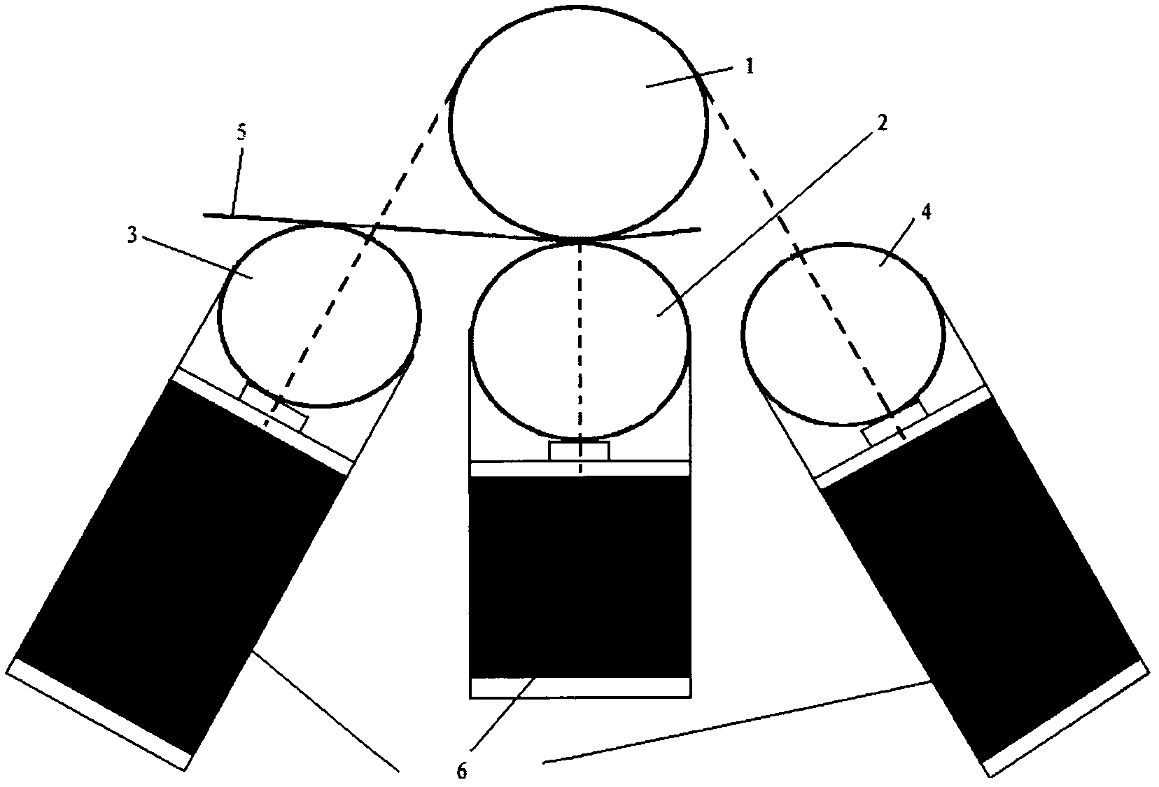
[0022] figure 1 Shown is the working principle diagram of the plate rolling machine. The upper roller 1 is fixed, the lower roller 2 moves vertically, and the front roller 3 and the rear roller 4 move along their respective tracks. figure 1 shown by the dotted line in . During the coiling process of the steel plate 5, the steel plate is first pressed by lifting the lower roller 2, and steel plates with different radii are rolled by lifting the height of the front roller 3 and the rear roller 4. The upper roller 1 and the lower roller 2 are always in a clamping state during the entire forming process of the sheet material 5, which enables the equipment to bend and form sheets of various thicknesses under its own maximum working capacity.

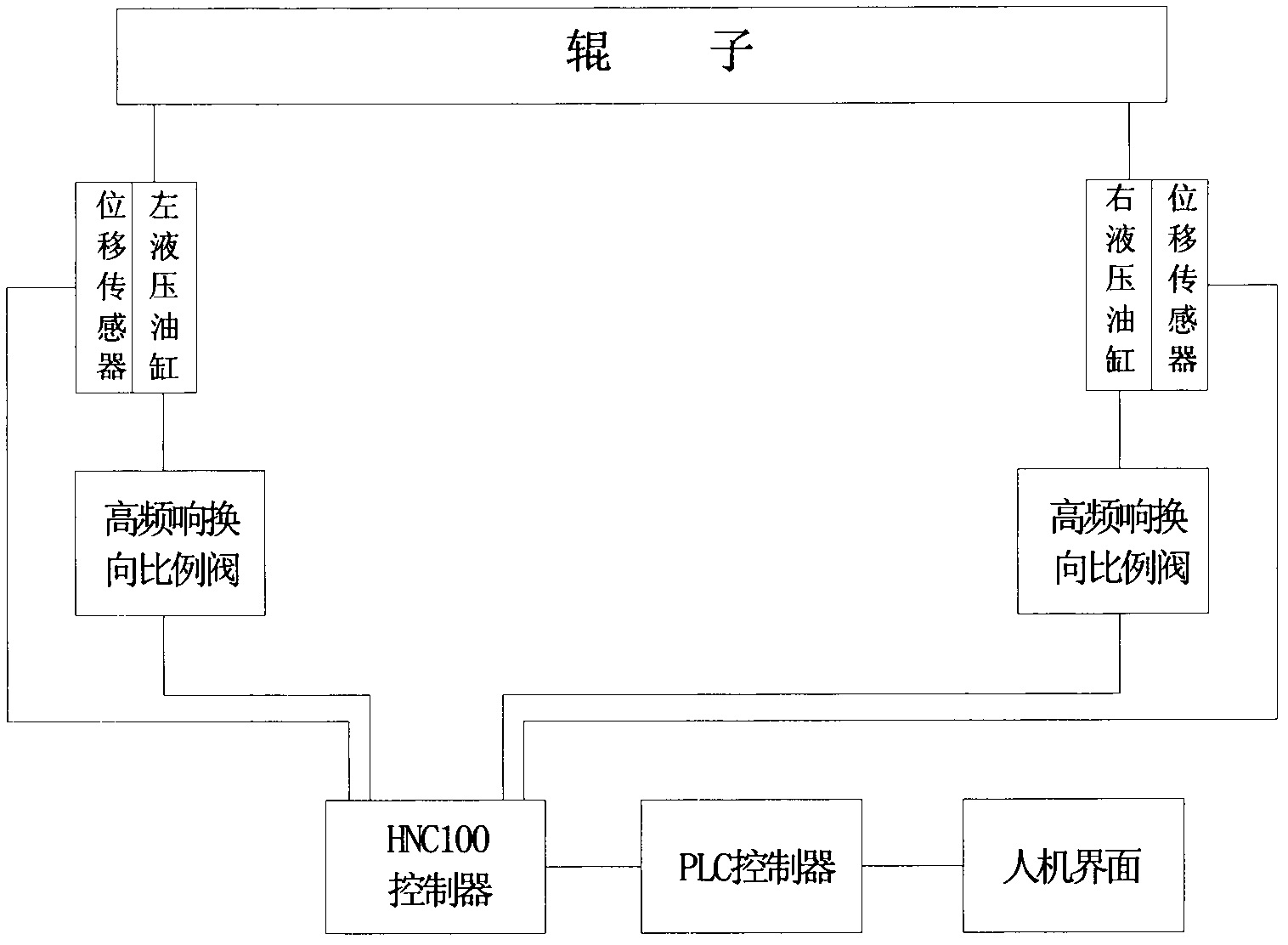
[0023] figure 2 Shown is the logical relationship diagram of the displacement closed-loop hydraulic control device, the PLC co...


PUM


Abstract

A lifting roller displacement control device in a plate rolling machine adopts a displacement closed loop hydraulic control system. The device structurally comprises a programmable logic controller (PLC), a higher national certificate (HNC) controller, a hydraulic cylinder, a proportional valve and a man-machine interface. A displacement detection sensor is installed on the hydraulic cylinder, and a pressure sensor is respectively installed on an oil path at two ends. Target displacement parameter manually set on the man-machine interface is transferred to the HNC controller which finishes comparison of input signals and feedback signals, the PLC adjusts openness and the open direction of the proportional valve, and hydraulic oil enters the hydraulic cylinder through the proportional valve to act on a piston and control lifting speed and lifting direction of a roller. The lifting roller displacement control device is capable of automatically controlling lifting action of the roller, high in automation degree, capable of dynamically monitoring the position of the roller in real time, capable of meeting requirements of plate rolling production for high efficiency, high accuracy and high specification due to the fact that the rolling plate process accuracy reaches +-0.2mm, good in overload protection and simple to operate.

Description

technical field [0001] The invention relates to a device for controlling the displacement of machine parts, in particular to controlling the displacement of rollers in a plate rolling machine. Background technique [0002] The plate rolling machine is a necessary mechanical equipment for the mechanical equipment industry, especially the container manufacturing industry. It is mainly used to roll different types of steel plates into cylindrical mechanical parts according to the design requirements, which belongs to mechanical processing equipment. In my country, there are already manufacturers producing plate rolling machines driven by motors or mechanical and hydraulic hybrid drives with a thickness of rolled steel plates below 180mm, but there are no domestic manufacturers of fully hydraulic plate rolling machines with a thickness of rolled steel plates exceeding 180mm, especially The large-scale plate rolling machine with mechanical, electrical and hydraulic integration is ...

Claims


Application Information

Patent Timeline
IPC IPC(8): B21D5/14
Inventor 向树民杨艳伟杨科张劲
Owner 西安兰石重工机械有限公司
Learn More