Electron beam welding method of gas turbine casing with horizontal flange structure

A technology of electron beam welding and gas turbine, which is applied in the direction of electron beam welding equipment, welding equipment, metal processing equipment, etc., can solve the problems of complex design and manufacture of tooling, low rate of reuse of tooling, and low production efficiency, and achieve small deformation and high production efficiency. Improved efficiency and good rigidity

Active Publication Date: 2013-03-27
HARBIN TURBINE
View PDF5 Cites 40 Cited by
  • Summary
  • Abstract
  • Description
  • Claims
  • Application Information

AI Technical Summary

Problems solved by technology

[0003] The present invention is to solve the technical problems of the existing semi-ring type gas turbine casing welding method, such as large deformation of the horizontal flange after welding, complicated tooling design and manufacture, low tooling reuse rate and low production efficiency, and provides a horizontal method. Electron Beam Welding Method for Blue Structure Gas Turbine Case

Method used


Image

  • Electron beam welding method of gas turbine casing with horizontal flange structure
  • Electron beam welding method of gas turbine casing with horizontal flange structure

Examples


specific Embodiment approach 1

[0018] Specific Embodiment 1: An electron beam welding method for a gas turbine casing with a horizontal flange structure in this embodiment is implemented in accordance with the following steps:

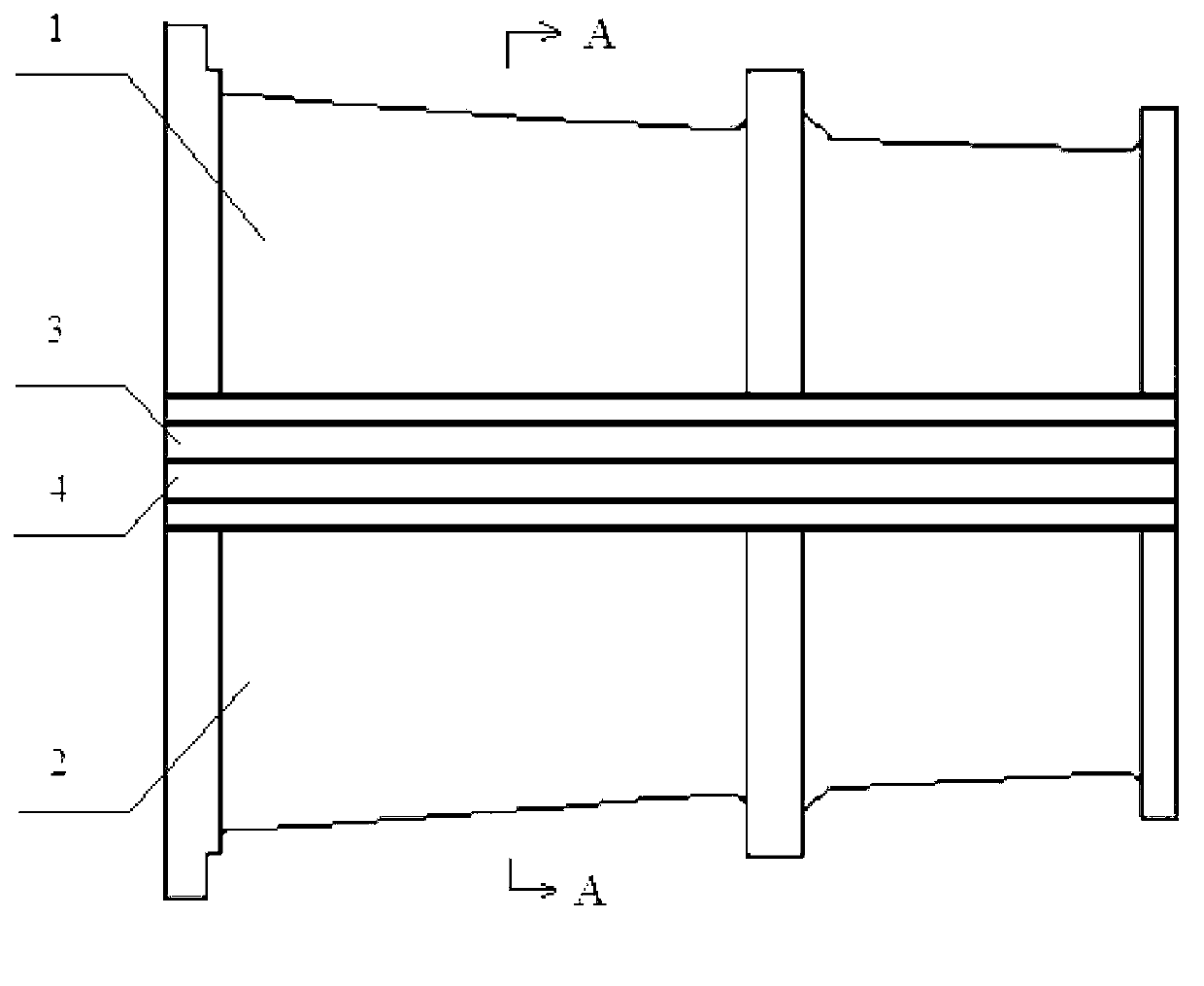
[0019] 1. Machining: Machining an opening groove inlaid with a pair of horizontal flanges on the casing body, after rotating the casing body 180°, machining an opening groove inlaid with a pair of horizontal flanges at the corresponding position to ensure The symmetry of the two grooves, the width of the opening groove is twice the height of a single horizontal flange, the length of the opening groove is the length of the horizontal flange, and there is a margin of 8~12mm between the two ends of the opening groove and the two ends of the casing body;

[0020] 2. Cleaning: Clean the surface of the casing body to be welded and the surface of the horizontal flange to be welded;

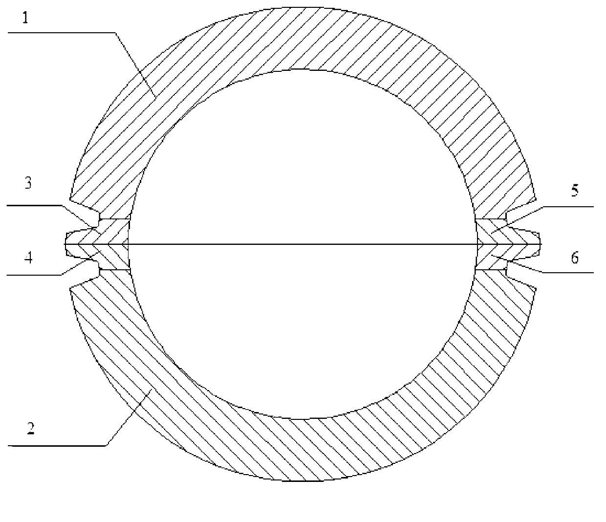
[0021] 3. Spot welding: Spot welding two or two pairs of horizontal flanges on the outer surface of the hor...

specific Embodiment approach 2

[0030] Embodiment 2: The difference between this embodiment and Embodiment 1 is that in Step 1, there is a margin of 10 mm between the two ends of the opening slot and the two ends of the casing barrel, and other steps and parameters are the same as Embodiment 1.

specific Embodiment approach 3

[0031] Embodiment 3: The difference between this embodiment and Embodiment 1 or 2 is that in Step 5, the gap between the horizontal flange and the casing body is 0.05-0.12 mm, and the wrong side is 0.02-0.08 mm. Other steps and parameters are the same as The specific embodiment 1 or 2 are the same.


PUM

PropertyMeasurementUnit
heightaaaaaaaaaa
diameteraaaaaaaaaa
diameteraaaaaaaaaa

Abstract

The invention discloses an electron beam welding method of a gas turbine casing with a horizontal flange structure, and relates to the welding method of the casing with horizontal flanges. The invention aims at solving the technical problems of large deformation, complicated tooling design and manufacture, low repetition usage rate of the tooling and low production efficiency after the horizontal flanges are welded by the existing half-ring gas turbine casing welding method. The welding method comprises the following steps of: 1, machining; 2, cleaning the surfaces of parts to be welded; 3, spot welding; 4, scribing; 5, assembling; 6, spot welding at fixed positions; 7, centering; 8, interpolating, and 9, welding the electron beam. Once vacuum electron beam welding of four horizontal flanges is achieved by the welding method disclosed by the invention; the deformation after welding is small; the production efficiency is doubled; X-ray flaw detection non-destructive testing is carried out; a welding line does not generate the defects such as lack of penetration, air holes, cracks and puncture; the quality of the welding line meets the requirements; and the electron beam welding method is simple in tooling design and manufacture, and high in repetition usage rate of the tooling, and can be used for welding the horizontal flanges of the gas turbine casing.

Description

technical field [0001] The invention relates to a method of welding casings with horizontal flanges. Background technique [0002] The electron beam welding of the horizontal flange of the gas turbine casing is a key part of the production. The casing structure requires high welding quality. In the existing half-ring casing horizontal flange welding method, the casing body is cut Form two half-ring cylinders, and then weld two horizontal flanges to the two ends of a half-ring cylinder respectively in two times. The welding process requires two vacuum electron beam welding. Before welding, the shape is forced to be corrected by the tooling. , the internal stress is large, the assembly is difficult, and the parts are deformed after welding, which seriously affects the welding quality, which directly affects the quality and production efficiency of the casing product, and also affects the manufacturing level of the gas turbine. In order to reduce the deformation of the casing,...

Claims


Application Information

Patent Timeline
Patent Type & Authority Applications(China)
IPC IPC(8): B23K15/06B23K28/02
Inventor 王金刚宫在龙太秀滨李绪瑞门士然陈丽娟彭勇韩志双邓萌于增杰
Owner HARBIN TURBINE
Why Eureka
Try Eureka