Extruding and grinding device for spray orifice of oil spray nozzle and extruding and grinding method for spray orifice of oil spray nozzle

A technology of extrusion grinding and oil injection nozzle, which is applied in the direction of grinding workpiece support, grinding/polishing equipment, metal processing equipment, etc., which can solve the problem of difficult to meet high-precision flow measurement, difficult to stabilize system pressure, high hydraulic oil requirements, etc. problems, to achieve the effect of facilitating daily production management, eliminating burrs, and improving process practicability

Active Publication Date: 2013-03-27
CHINA FIRST AUTOMOBILE
View PDF9 Cites 14 Cited by
  • Summary
  • Abstract
  • Description
  • Claims
  • Application Information

AI Technical Summary

Problems solved by technology

The disadvantages of this method are as follows: the hydraulic oil for driving and the slurry for grinding are stored in a high-pressure material tank at the same time. In order to separate the two, the high-pressure material tank adopts a special structure. The system pressure is difficult to stabilize, and it is difficult to meet the requirements of high-precision flow measurement; on the other hand, this method involves a complex hydraulic system, and various pumps and valves have high requirements for hydraulic oil, resulting in high maintenance costs and high failure rates of the system

Method used


Image

  • Extruding and grinding device for spray orifice of oil spray nozzle and extruding and grinding method for spray orifice of oil spray nozzle

Examples


Embodiment Construction

[0026] The specific implementation manner of the present invention will be described below in conjunction with the accompanying drawings.

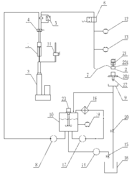
[0027] See figure 1 , the injector orifice extrusion grinding device of the present invention comprises an electric cylinder 3, the electric cylinder 3 is driven and connected with the abrasive cylinder 1, and the piston of the electric cylinder 3 drives the piston of the abrasive cylinder 1 to reciprocate, and the abrasive cylinder 1 is sequentially connected through pipelines. Reversing valve 4, filter 5, shut-off valve-6 and high-pressure hose 7, pressure sensor 12 and temperature sensor-13 are connected through pipelines between shut-off valve-6 and high-pressure hose 7, and high-pressure hose 7 is connected to the clamp 2. The clamp 2 includes a clamp pressure head 201 and a clamp base 202. The clamp pressure head 201 has a flow channel connected to the small hole of the processed part. The high-pressure hose 7 is connected to the cla...


PUM


Abstract

The invention provides an extruding and grinding device for a spray orifice of an oil spray nozzle and an extruding and grinding method for the spray orifice of the oil spray nozzle, belonging to the technical field of the precision machining of the spray orifice of the oil spray nozzle. The extruding and grinding device for the spray orifice of the oil spray nozzle provided by the invention comprises a grinding material filling pipeline, a grinding material processing pipeline, a grinding material emptying pipeline, a grinding material temperature control pipeline and an emergency emptying pipeline, wherein a detecting device is arranged on the grinding material processing pipeline for detecting the real-time grinding material flow of the spray orifice of the oil spray nozzle. The extruding and grinding method for the spray orifice of the oil spray nozzle provided by the invention mainly comprises the following steps of: grinding-detecting and comparing flow-grinding-detecting and comparing flow. The spray orifice of the oil spray nozzle is machined by means of extruding and grinding by a step-by-step approach method. According to the method, the real-time grinding material flow of the spray orifice is accurately detected and is compared step by step till the flow value reaches a set value, so that the grinding processing can be guaranteed to achieve the technological requirement. According to the invention, the filleted corner of the orifice, which accords with the technological requirement, can be formed, so that the fineness of the wall of the spray orifice can be improved, the flow coefficient of the oil spray nozzle can be improved, and the device is simple in structure and convenient to maintain.

Description

technical field [0001] The invention relates to the technical field of precision machining, in particular to the precision machining of tiny holes in parts, in particular to a squeeze grinding device for a nozzle hole of a fuel injection nozzle for a diesel engine and a flow control method for the nozzle hole. Background technique [0002] The fuel injector is one of the important components in the fuel system of a diesel engine. With the improvement of national emission requirements and the application of high-pressure common rail technology, the fuel injector is also developing in the direction of the number of holes and small aperture, and its processing quality directly affects the fuel injector. The atomization characteristics, oil line penetration and flow coefficient of the diesel engine will ultimately affect the economy, power and emission indicators of the diesel engine. Among them, the nozzle flow coefficient is an important index for evaluating the quality of the ...

Claims


Application Information

Patent Timeline
Patent Type & Authority Applications(China)
IPC IPC(8): B24B39/02B24B41/06B24B57/02
Inventor 吴欲龙唐维平张丽敏周毅吴克忠吴淳武
Owner CHINA FIRST AUTOMOBILE
Why Eureka
Try Eureka