
Gas-liquid heat exchange type refrigeration device

A gas-liquid heat exchanger and refrigeration device technology, applied in refrigerators, refrigeration components, refrigeration and liquefaction, etc., can solve problems such as changes in heat exchange performance of gas-liquid heat exchangers, deterioration of refrigerator oil, and rise in refrigerant discharge temperature. Achieve the effects of suppressing poor cooling, preventing freezing, and suppressing the rise in discharge temperature

Active Publication Date: 2013-03-27
TOPRE
View PDF7 Cites 5 Cited by
  • Summary
  • Abstract
  • Description
  • Claims
  • Application Information

AI Technical Summary

Problems solved by technology

[0009] However, if the refrigerating and air-conditioning apparatus proposed in Patent Document 1 is operated in an environment where the number of revolutions of the compressor greatly fluctuates, such as in a refrigerated vehicle, the heat exchange performance of the gas-liquid heat exchanger will also be accompanied by compression. The number of revolutions of the machine changes greatly
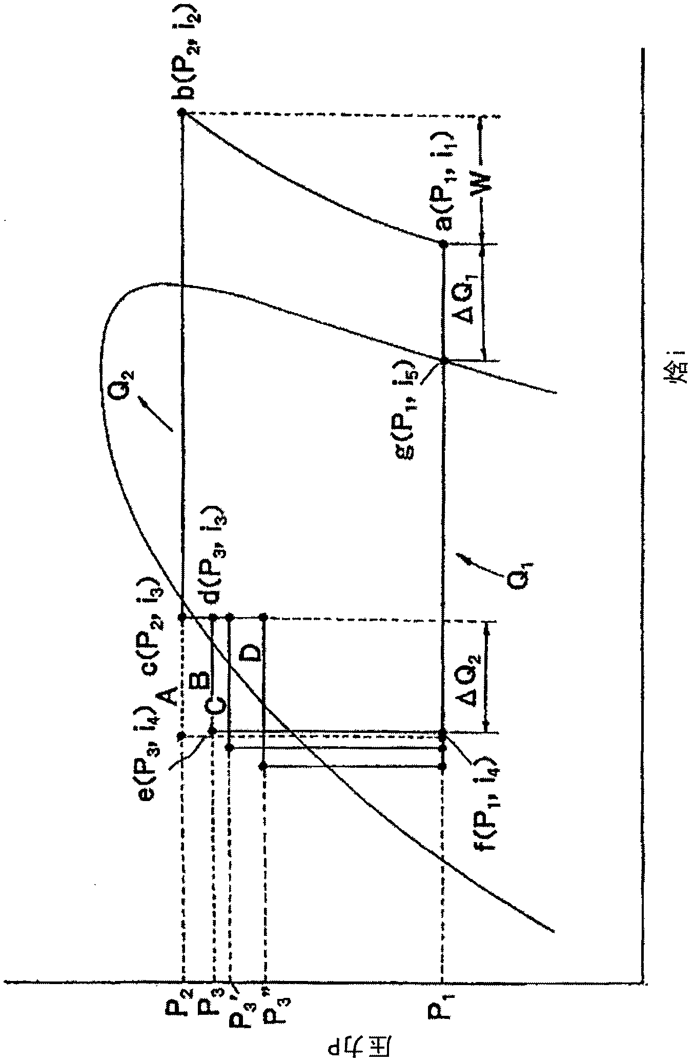
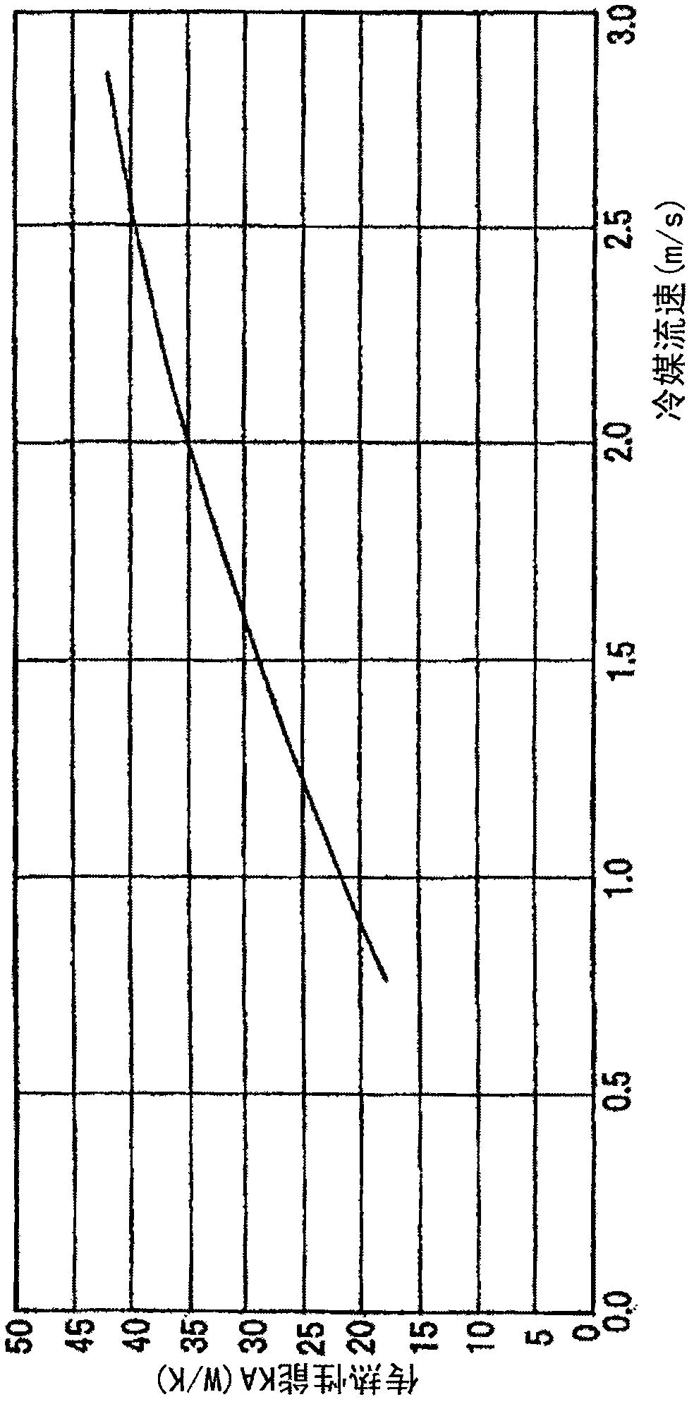
For example, if the number of revolutions of the compressor decreases, the amount of refrigerant circulation decreases, and poor cooling occurs due to insufficient heat exchange in the gas-liquid heat exchanger. On the contrary, if the number of revolutions of the compressor increases, the amount of refrigerant circulation increases. , due to the excessive heat exchange, the discharge temperature of the refrigerant at the outlet of the compressor rises, and problems such as deterioration of the refrigerator oil occur.

Method used


Image

  • Gas-liquid heat exchange type refrigeration device
  • Gas-liquid heat exchange type refrigeration device
  • Gas-liquid heat exchange type refrigeration device

Examples


Embodiment Construction

[0035] Hereinafter, embodiments of the present invention will be described with reference to the drawings.

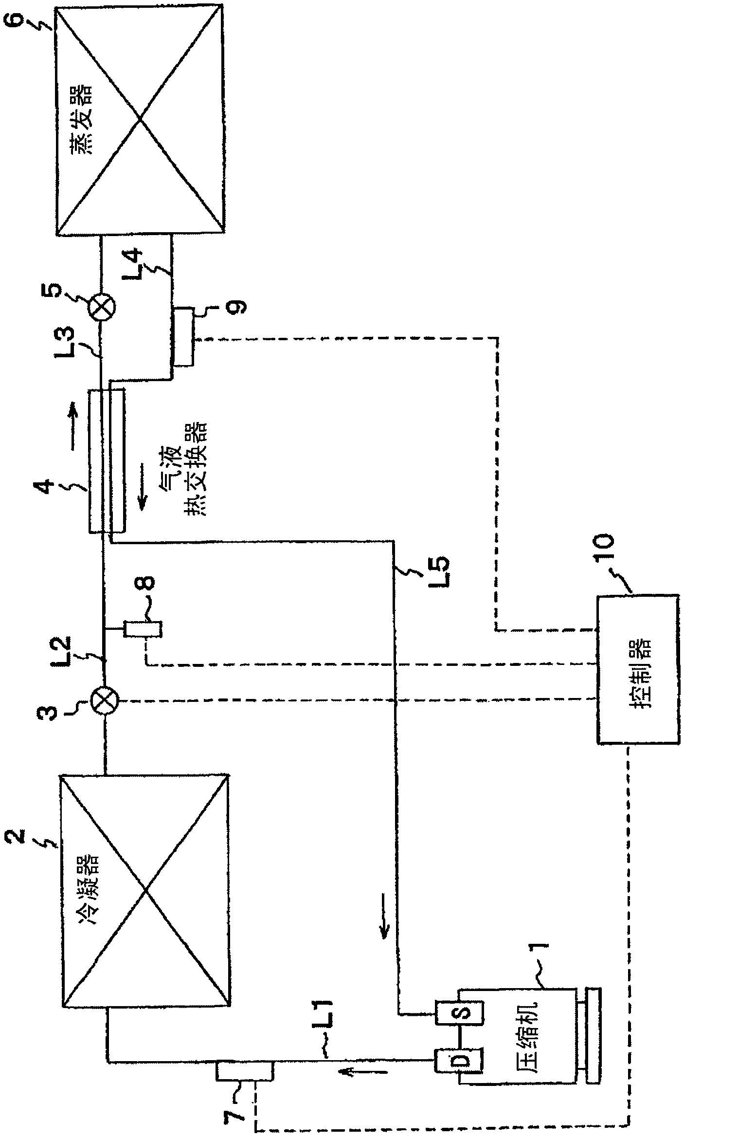
[0036] figure 1 It is a refrigerant circuit diagram of the gas-liquid heat exchange type refrigeration device of the present invention. In the gas-liquid heat exchange type refrigeration device shown in the figure, a compressor 1, a condenser 2, a heat exchange control valve 3, a gas-liquid heat exchanger 4, The expansion valve 5 and the evaporator 6 are connected in series by refrigerant lines L1 , L2 , L3 , L4 , and L5 to form a closed refrigerant circulation circuit. Here, the heat exchange control valve 3 is arranged on the refrigerant pipeline L2, and the refrigerant pipeline L2 is used to connect the condenser 2 and the gas-liquid heat exchanger 4; the expansion valve 5 is arranged on the refrigerant pipeline L3 , the refrigerant pipeline L3 is used to connect the gas-liquid heat exchanger 4 and the evaporator 6 . In addition, the heat exchange control valve 3 i...


PUM


Abstract

The invention discloses a gas-liquid heat exchange type refrigeration device. Refrigeration capability variations caused by the variations of the turnover number of a compressor can be suppressed, and the rise of discharge temperature at an outlet of the compressor can be suppressed to prevent refrigerator oil from being degraded. The liquid-gas heat exchange type refrigeration device consists of the compressor 1, a condenser 2, a heat exchange control valve 3, a gas-liquid heat exchanger 4, an expansion valve 5 and an evaporator 6, which are connected in series through a coolant pipeline to form a closed coolant circulation pipeline. A discharge temperature sensor 7 is arranged between the compressor 1 and the condenser 2 of the coolant circulation loop. A pressure sensor 8 is arranged between the heat exchange control valve 3 and the gas-liquid heat exchanger 4. A controller (control device) 10 is also arranged to control the opening of the heat exchange control valve 3 on the basis of coolant temperature detected by the discharge temperature sensor 7 at the outlet of the compressor 1 and coolant pressure detected by the pressure sensor 8 at an outlet of the heat exchange control valve 3.

Description

technical field [0001] The invention relates to a gas-liquid heat exchange type refrigeration device, which uses the refrigerant condensed by the condenser and the refrigerant evaporated by the evaporator to exchange heat with each other in a gas-liquid heat exchanger, so that each refrigerant is overcooled and cooled separately. Overheating, thereby increasing the freezing capacity. Background technique [0002] Generally speaking, a refrigeration device is a closed-circuit refrigerant circulation loop composed of a refrigerant pipeline connecting a compressor, a condenser, an expansion valve, and an evaporator in series. The high-pressure gaseous refrigerant compressed by the compressor is released in the condenser. It releases heat and liquefies to become a high-pressure liquid refrigerant. After the expansion valve expands the liquid refrigerant (isoenthalpic expansion) and decompresses it, in the evaporator, the low-pressure liquid refrigerant whose boiling point has be...

Claims


Application Information

Patent Timeline
IPC IPC(8): F25B49/02
Inventor 渡边健太郎
Owner TOPRE
Learn More