

Micro-strip antenna unit and array thereof
A technology of microstrip antenna and microstrip line, which is applied in the directions of antenna array, antenna, antenna coupling, etc., can solve the problems that the gain value of the microstrip antenna and the dual polarization feed isolation can not meet the use requirements, and the use loss is large, etc., to achieve Suitable for industrial production, improved isolation, and less loss
- Summary
- Abstract
- Description
- Claims
- Application Information
AI Technical Summary
Problems solved by technology
Method used
Image

Examples
Embodiment Construction
[0018] The present invention will be further elaborated below in conjunction with the accompanying drawings.
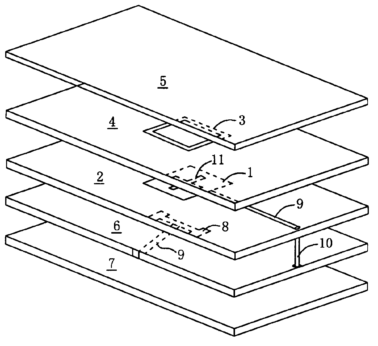
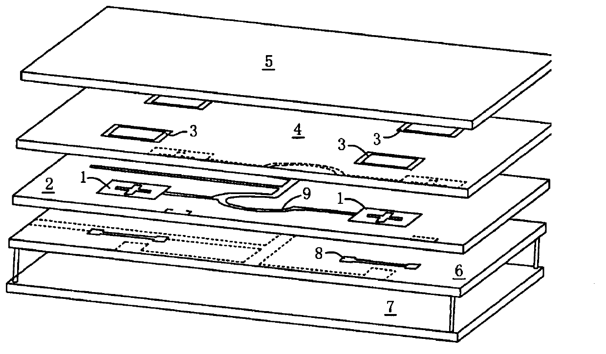
[0019] refer to figure 1 As shown, one embodiment of the present invention is a microstrip antenna unit, which includes a first dielectric substrate 2 with a main radiation patch 1 above and a second dielectric substrate 4 with a parasitic patch 3 above, and the first Two dielectric substrates 4 are arranged above the first dielectric substrate 2; a covering dielectric plate 5 is arranged above the second dielectric substrate 4, and a grounding plate 6 is arranged below the first dielectric substrate 2; reflector 7, the reflector 7 is made of metal, and its function is to make the energy radiated by the main radiation patch 1 more concentrated; The H-shaped slot 8 is connected to the microstrip line 9 used for feeding, and in order to ensure high isolation in the use of dual-polarization feeding, it is also necessary to place the microstrip line 9 on the lower side o...
PUM
 Abstract
Description
Claims
Application Information