Unloading one-way valve applied to back flushing and dust cleaning system of dust collector

A technology of one-way valves and vacuum cleaners, which is applied in the direction of machines/engines, liquid displacement machinery, variable displacement pump components, etc. It can solve the problems that the unloading pressure cannot be adjusted, the compressed air cannot be discharged, and the motor and compressor are damaged. , to achieve the effect of reliable work, simple structure and easy installation

Active Publication Date: 2013-04-03
HUSQVARNA AB
View PDF7 Cites 4 Cited by
  • Summary
  • Abstract
  • Description
  • Claims
  • Application Information

AI Technical Summary

Problems solved by technology

[0004] For this reason, some air compressor systems have adopted a kind of unloading check valve to carry out unloading, as the patent of invention that the authorized announcement number is CN 2199389Y explains that the unloading check valve of a kind of air compressor disclosed, this The valve can replace the air pressure automatic switch on the micro air compressor, but the structure is complicated, and many components are used. There are complicated connections such as copper pipes and mechanical lever switches. The compressed air cannot be discharged. If it needs to be turned on again, it needs to be manually vented. If it is not handled properly, it will damage the motor and compressor.
Another example is the CN 1896574A patent for invention, which discloses a kind of unloading check valve for an air compressor. The valve has the following two defects, one is poor reliability, the rubber seal has relative movement with the vent groove and air intake groove, which can easily damage the seal and cause the seal to fail, and the other is that the unloading pressure of the valve cannot be adjusted

Method used


Image

  • Unloading one-way valve applied to back flushing and dust cleaning system of dust collector
  • Unloading one-way valve applied to back flushing and dust cleaning system of dust collector
  • Unloading one-way valve applied to back flushing and dust cleaning system of dust collector

Examples


Embodiment 1

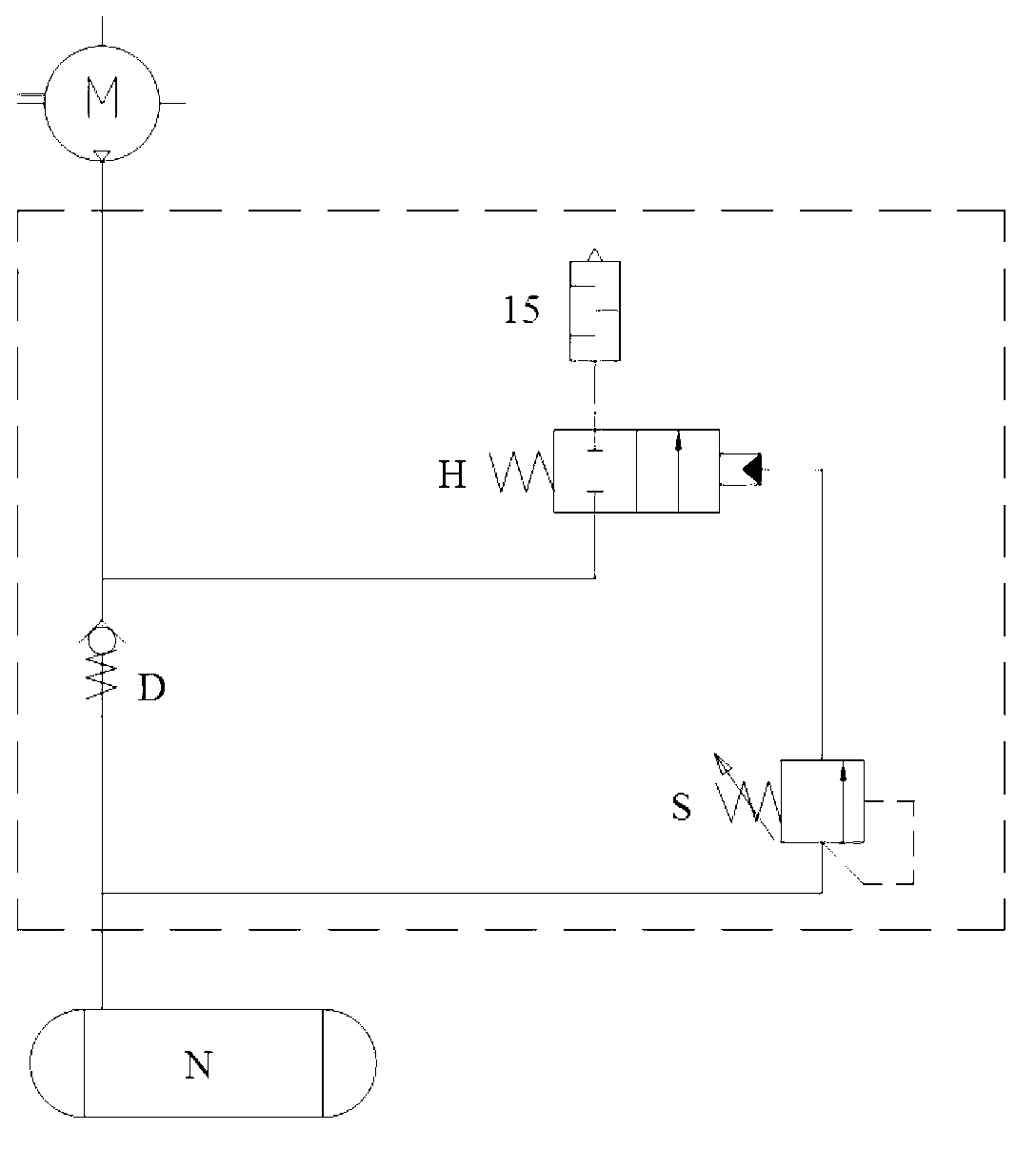
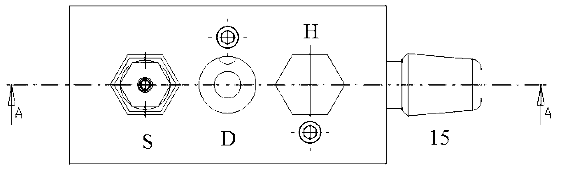
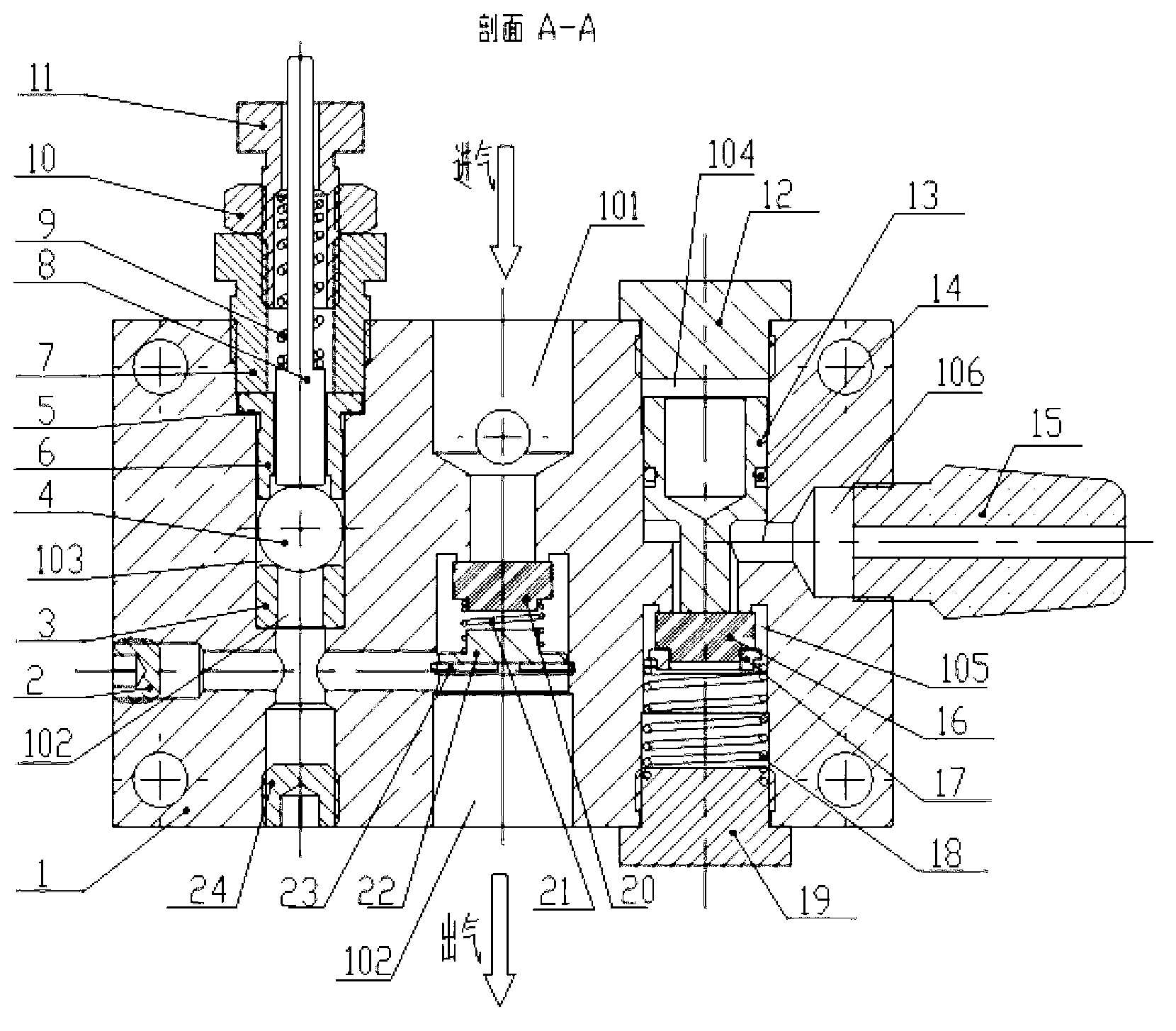
[0028] Such as figure 1 As described above, an unloading check valve applied to the dust cleaning system of a vacuum cleaner, the unloading check valve includes a valve body 1, and a check valve D, a sequence valve S and a reversing valve integrated on the valve body H, one end of the one-way valve D is connected to the air compressor M through the inlet pipe, and the other end is connected to the air tank N through the outlet pipe. The sequence valve S is respectively connected to the one-way valve D and the reversing valve H, and The valve H is connected to the muffler 15. When working, the pressure is set through the sequence valve S. This pressure is the working pressure required by the compressed air of the air storage tank N. When the compressed air output by the air compressor M makes the compressed air in the air storage tank N When the working pressure is reached, the sequence valve S is opened, and the air flow activates the reversing valve, so that the air is direct...


PUM


Abstract

The invention relates to an unloading one-way valve applied to a back flushing and dust cleaning system of a dust collector. The unloading one-way valve comprises a valve body as well as a one-way valve, a sequence valve and a reversing valve which are integrated on the valve body, wherein one end of the one-way valve is connected with an air compressor through an air intake pipe, and the other end of the one-way valve is connected with an air storage tank through an air exhaust pipe; the sequence valve is respectively communicated with the one-way valve and the steering valve; the reversing valve is connected with a silencer; when the unloading one-way valve works, the sequence valve sets pressure, namely the working pressure required for compressed air of the air storage tank; and when the compressed air output by the air compressor enables the compressed air in the air storage tank to reach the working pressure, the sequence valve is opened, the reversing valve is started by air flow, so that air is exhausted directly by the silencer, and air inflation to the air storage tank is stopped, and at the moment, the one-way valve is closed. Compared with the prior art, the unloading one-way valve disclosed by the invention has the advantages of simple structure, easy machining, high integration degree, small size, reliability, convenience for maintenance and the like.

Description

technical field [0001] The invention relates to an unloading one-way valve, in particular to an unloading one-way valve applied to a dust cleaning system of a vacuum cleaner. Background technique [0002] At present, the displacement of air compressors used in mobile industrial vacuum cleaners with back-blowing and dust-cleaning systems at home and abroad is basically small air compressors, and the air pressure automatic switch is used to control and adjust the exhaust pressure. When the stop pressure set by the pressure relay is reached, the motor of the air compressor will automatically stop running under the control of the switch. The press performs the inflation work again. This method has the effect of saving energy to a certain extent, but if the on-site gas consumption is large and the limited capacity of the gas storage tank received by the equipment is constant, the start-up of the air compressor will become frequent, which will cause great damage to the motor, and...

Claims


Application Information

Patent Timeline
Patent Type & Authority Applications(China)
IPC IPC(8): F04B39/10
Inventor 罗智
Owner HUSQVARNA AB
Why Eureka
Try Eureka