Biomass power plant smoke wind waste heat recovery device

A waste heat recovery and biomass technology, which is applied in preheating, steam generation, feed water heaters, etc., can solve the problems of difficult recovery and utilization of flue gas waste heat, and achieve high heat recovery and utilization rate

Inactive Publication Date: 2016-01-06
ZHEJIANG GONGSHANG UNIVERSITY
View PDF7 Cites 1 Cited by
  • Summary
  • Abstract
  • Description
  • Claims
  • Application Information

AI Technical Summary

Problems solved by technology

[0003] Aiming at the problem that the flue gas waste heat in the prior art is difficult to recover and utilize, the present invention provides a biomass power plant flue gas waste heat recovery device that adopts heat pump technology to recover the flue gas waste heat of the power plant

Method used


Image

  • Biomass power plant smoke wind waste heat recovery device

Examples


Embodiment Construction

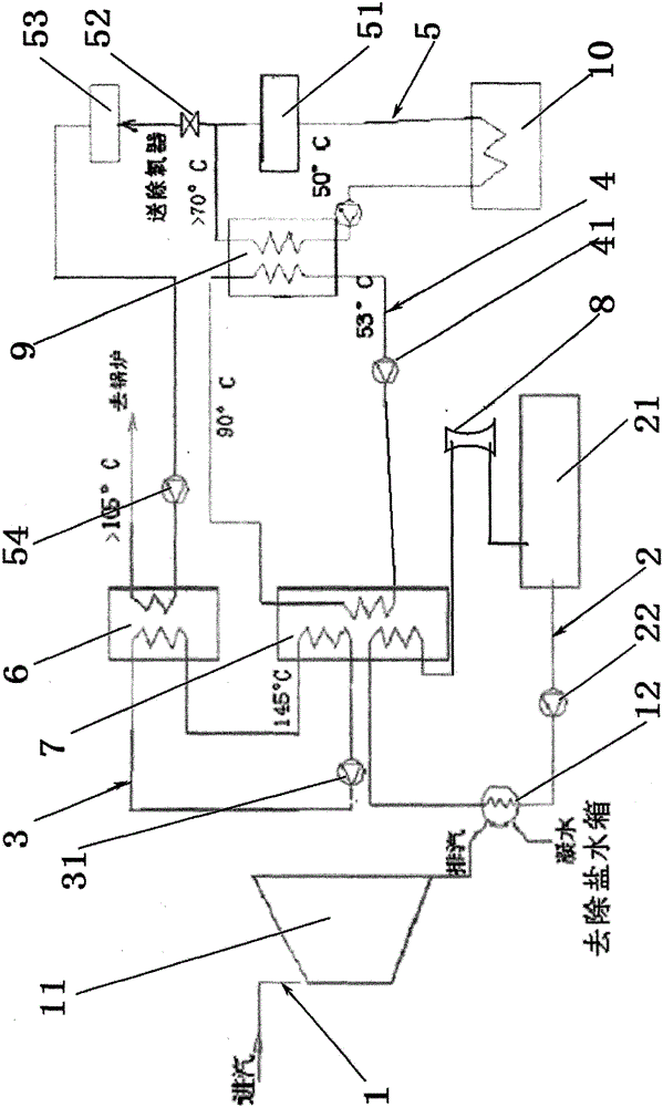
[0013] Attached below figure 1 The present invention is described in further detail with the specific embodiment:

[0014] A biomass power plant smoke wind waste heat recovery device, such as figure 1 As shown, it includes a steam pipeline 1 , a cooling water circulation pipeline 2 , a flue gas heat exchange pipeline 3 , an internal circulation pipeline 4 and a demineralized water pipeline 5 .

[0015] The steam pipeline 1 connects the steam turbine 11 and the condenser 12; the cooling water circulation pipeline 2 starts from the cooling circulation pool 21, passes through the condenser 12, the absorption heat pump 7 and the cooling tower 8, and then returns to the cooling circulation pool 21. The steam generated by the steam turbine 11 is sent to the condenser 12, and the steam passes through the condenser 12 to transfer heat energy to the cooling water in the cooling water circulation pipeline 2, and the cooling water with heat energy passes through the absorption heat pump...


PUM


Abstract

The invention relates to a heat recovery device, and discloses a flue gas waste heat recovery device of a biomass power plant. The flue gas waste heat recovery device comprises a steam line, a cooling water circulation line, a desalted water line and a flue gas heat exchange line, wherein a flue gas heat exchanger is arranged on the flue gas heat exchange line, and flue gas returns to the flue gas heat exchanger after heat is absorbed by an absorption heat pump. The flue gas waste heat recovery device recovers waste heat in flue gas and slag of the biomass power plant in a heat exchange mode and has the advantages of high recovery use ratio of heat energy, energy conservation, environmental protection and the like.

Description

technical field [0001] The invention relates to a heat recovery device, in particular to a waste heat recovery device for flue gas from a biomass power plant. Background technique [0002] The flue wind heat of the biomass power plant is discharged into the atmosphere through the chimney to form a huge loss of heat energy, which is the main reason for the low efficiency of energy use in the biomass power plant. It not only causes waste of energy and water or electricity, but also seriously pollutes the atmosphere. An important difference between biomass power plants and thermal power plants is that the sulfur content in the combustion exhaust gas of biomass power plants is extremely low, and sulfuric acid will not be formed after condensation, which will corrode equipment. Therefore, the biomass power plant does not have certain temperature requirements for the flue gas it emits, and the heat in the flue gas can be completely recycled. Contents of the invention [0003] A...

Claims


Application Information

Patent Timeline
Patent Type & Authority Patents(China)
IPC IPC(8): F22D1/00
Inventor 李同强张新波
Owner ZHEJIANG GONGSHANG UNIVERSITY
Why Eureka
Try Eureka